Chapter E: CALIBRATIONS 1 ADJUSTING AND CALIBRATING X-RAY BEAM
Technical manual Planmeca ProOne 105
Check that the line on the underside of the alignment ruler coincides with the x-line on the
ball phantom. Observe the ruler position from below the ball phantom.
If the lines do not coincide, compare the distances between the line on the alignment ruler
and the x-line on the ball phantom when the C-arm is in position X1 and X2. If the
deviation is more than 1mm, you will have to adjust the sensor position.
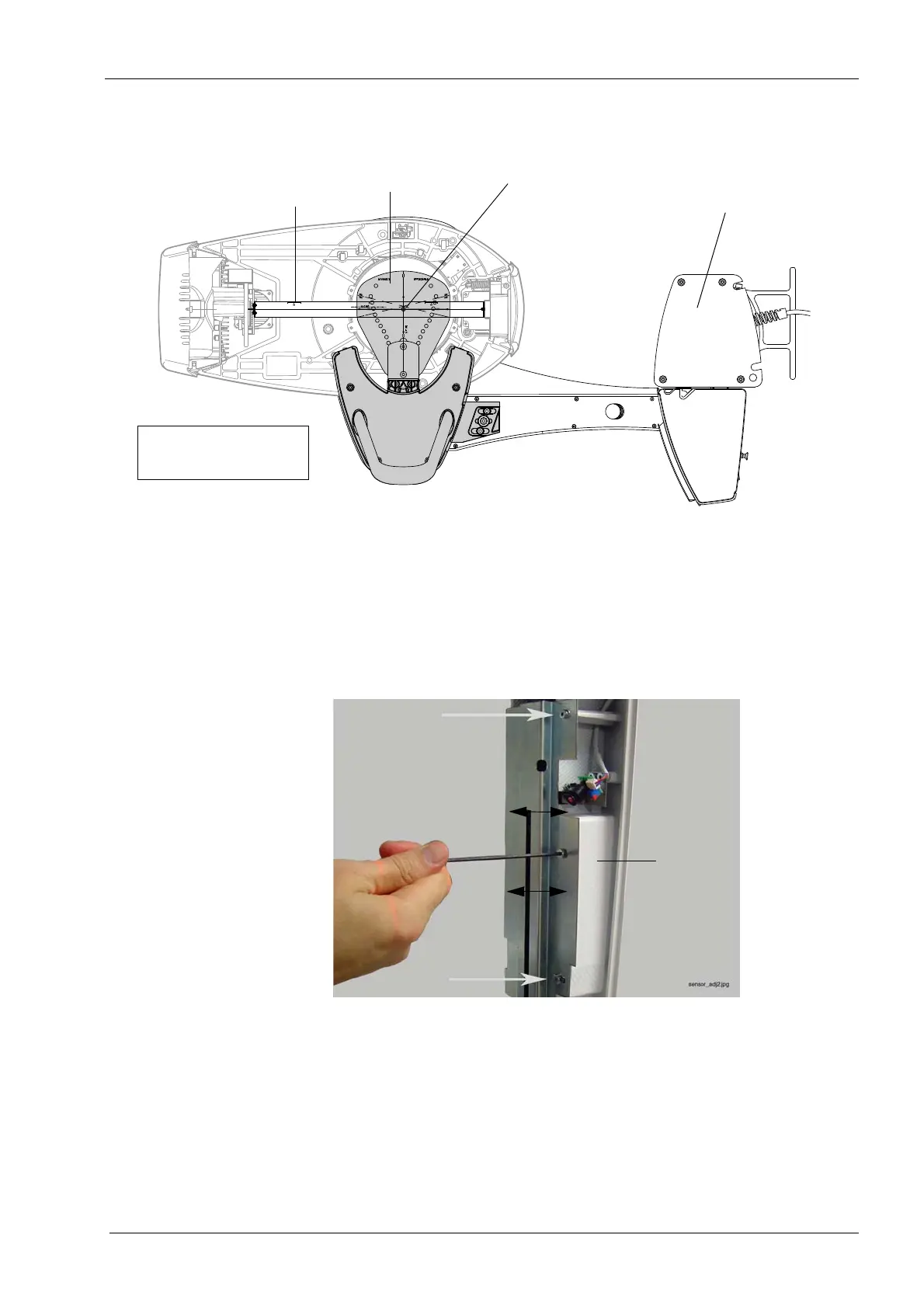
To do this, loosen the three screws that hold the sensor in position and carefully move the
sensor towards the x-line on the ball phantom until the distance is less than 0.5mm.
Correct only half of the deviation, so that the deviation will be the same in both positions
(C-arm pos. X1 and X2).
Tighten the three screws. Exit the
Patient support calibration (T3430)
display by touching
the green check mark button in the bottom right corner.
Repositioning the sensor will move the beam position, i.e. you will have to remove the
alignment ruler and start again from Step 1, see section 1.4 "Step 1: Adjusting the X-ray
beam position" on page 92.
When C-arm positions X1 and X2 are symmetrical, remove the alignment ruler and
proceed to Step 5.
Alignment ruler
Ball phantom
Tube head side
Sensor head side
Lines must coincide
C-arm in X2-position;
bottom view
Column
Tube head side
Sensor head side
Ball phantom
Alignment ruler
Lines must coincide

 Loading...


