Chapter G: DIAGRAMS 1 WIRING DIAGRAMS
Technical manual Planmeca ProOne 185
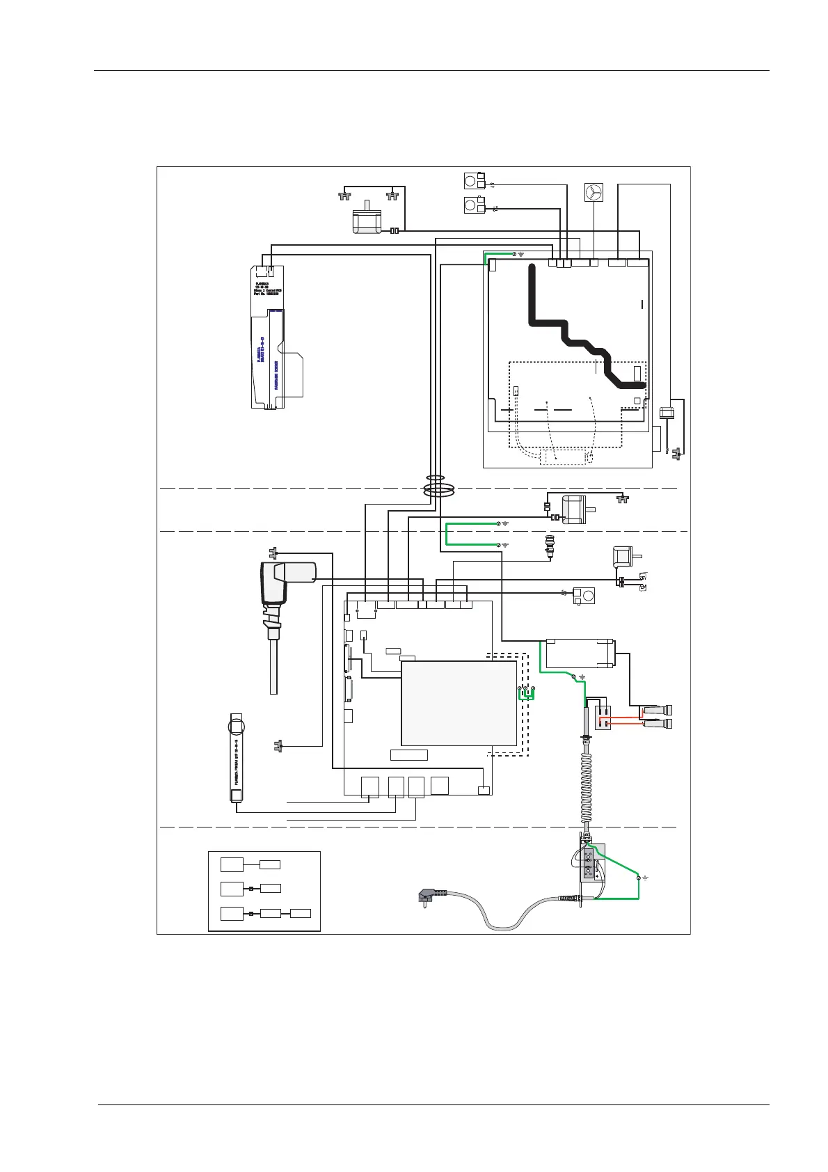
1.2 Wiring diagram for X-ray units with detachable power supply cord
Upper Arm
Moving Column
St at i o n ar y Co l u m n
ProOne Wiring Diagram
12.11.2014 LY
Tub eh ead
IMS PCB
7005-10-06
Dimax
Exposure Switch Configurations
Pr o On e
Pr o On e
Pr o On e
EXP sw
Fi xe d
EXP sw
Fi xe d
EXP sw
Fi xe d
EXP sw
10012345
10012346
10015294
10012346
10016305
10012359
10013177
10012365
10012360
1001236110012361
10012358
10012355
10012349
FIL PCB
7005-10-08
10013178
10013828
10012351
10012357
10012363
10012352
10026686
10012347
10012347
10012363
10012353
10012353
10012354
10012354
10012343 EU
10012344 USA
10017649 China
10037466 AUS
L
N
Tem p le
Support
Em e r g e n c y
Sw i t c h
Linear
Motor
Lift
Motor
Pr i m ar y
Sl o t
Motor
Midsagittal Laser
Layer Laser
Fan
Fr an k f or t Laser
Et h e r n e t
Rotation
Motor
Limi t
Se n s o r
10012350
Limit
Se n so r
Exposure Swit ch Cable 10001193
Remote Exposure Option
EXP PCB
121-10-15
Tu be
Feedback&
Fi l am en t
PSU PCB
7005-10-01
J1
CAN
Mains
Collimator
Motor
Rotation
Motor
Layer
Laser
Dim ax
Po w er
Mids
Laser
Fan
Tu be
Po w er
J2 J3 J4 J5 J6 J7 J8
J9
J1 0
J1 3 J1 4 J1 5 J1 6
J1 2
J1 1
10012356
J1
Cam e r a
To uc h
Pan e l
Bac k
Lig ht
Bac k Li gh t
CAN
Lin ear
Motor
Ex p Swi t c hEt h e r n e t USB
Lif t
Motor
Lif t
Upper
Lim it
Lif t
Low er
Lim it
Em e .
Sw .
Tem p le
Motor+
Lim it s
Fr an k
Laser
J2
J1 2
J1 9
J2 0J2 2
Ex p Swi t c h
J2 1J2 3
GUI
CPU PCB
7005-10-02
J1 4
J1 3
J1 1
J1 0
J3 J4
J5
J6
J7
J8
J9
GUI
J1
J2J3
121-10-08
121-10-08
121-10-08
J4 J5
HVR PCB
7005-10-03
(in oil chamber)
X-Ray
Tu be
10012364
10015015