3 COLUMN PARTS REPLACEMENT Chapter F: PARTS REPLACEMENT AND REPAIR
126 Planmeca ProOne Technical manual
3.3 Replacing the CPU PCB
The X-ray unit contains live mains voltage parts. Always disconnect the X-ray unit
from the mains before replacing the CPU PCB.
Open the front panel of the moving column as described in section 1.1 "Opening the front
panel" on page 117.
Remove the cable clamp above the CPU PCB by unscrewing the two screws that hold the
clamp in position.
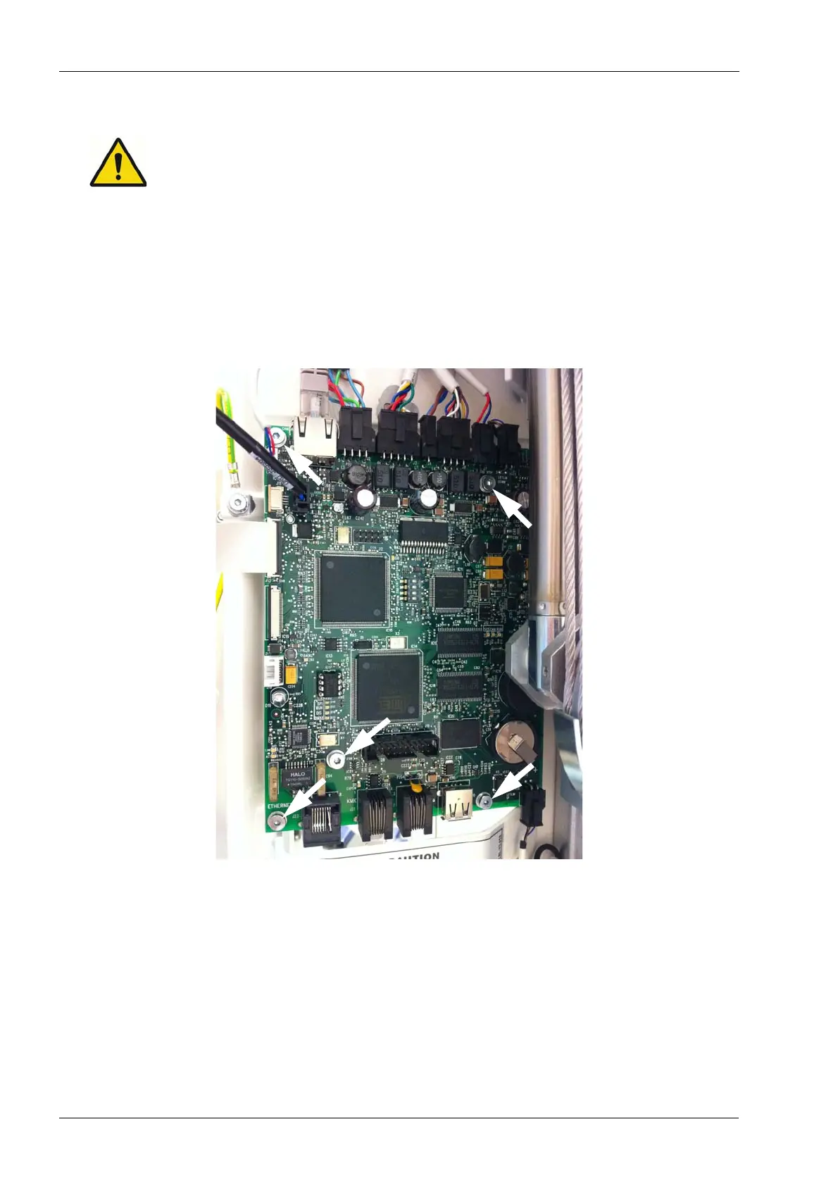
To remove the CPU PCB, first disconnect all cables from the PCB. Then remove the five
screws that secure the PCB to the column frame (shown below with white arrows).
Using the tip of a small screwdriver, carefully detach the EEPROM memory chip from the
old CPU PCB (socket IC17). All calibration data and settings for the X-ray unit are stored
in the EEPROM chip.
Antistatic precautions must be performed when handling the EEPROM chip. Touch any
grounded metal part of the X-ray unit before touching the software chip.