Chapter F: PARTS REPLACEMENT AND REPAIR 3 COLUMN PARTS REPLACEMENT
Technical manual Planmeca ProOne 125
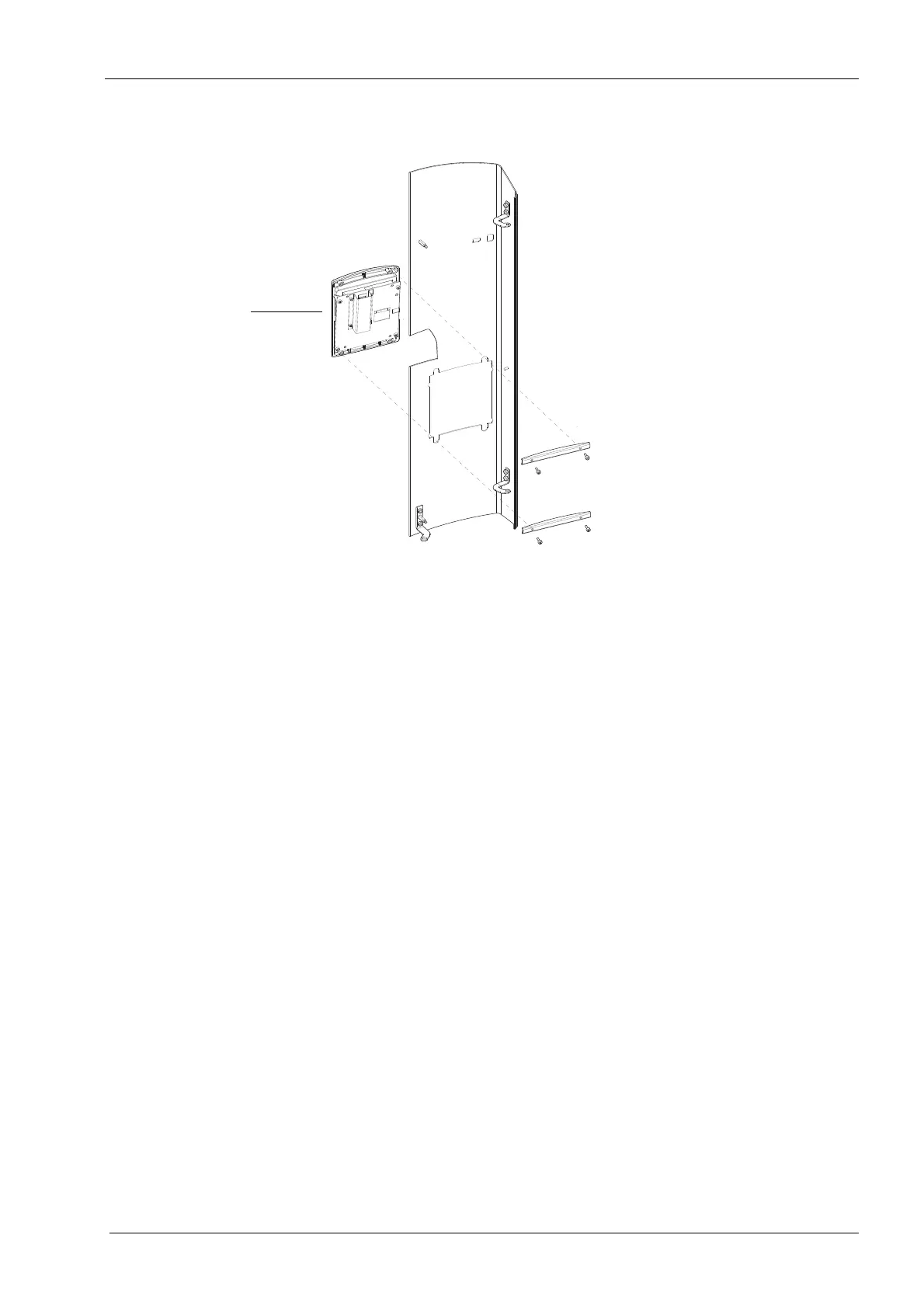
Now unscrew the four screws that hold the control panel in position.
Install a new control panel in reverse order.
All cables and cable connectors are labeled for easy reference and assembly.
When connecting the control panel flat cable, ensure that the cable does not get twisted
and that the side with the coloured mark faces outward.
 Loading...


