Chapter F: PARTS REPLACEMENT AND REPAIR 4 C-ARM AND UPPER ARM PARTS REPLACEMENT
Technical manual Planmeca ProOne 155
Install a new Power Supply Unit (PSU) assembly in reverse order.
When reconnecting the cables note that both the cables and the cable connectors are
labeled for easy reference and assembly.
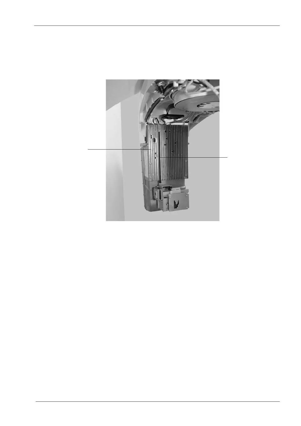
When reconnecting the collimator step motor cable (10012360 - J7) route the cable in one
of the grooves in the PSU assembly front grid as shown. This is to avoid problems when
reattaching the tube head covers.
Perform the X-ray tube filament definition as described in section 4.3.1 "Filament definition"
on page 159.
PSU assembly
front grid
Step motor cable