Chapter G: DIAGRAMS 4 CPU PCB (7005-10-02): Location of indicators and connectors
Technical manual Planmeca ProOne 191
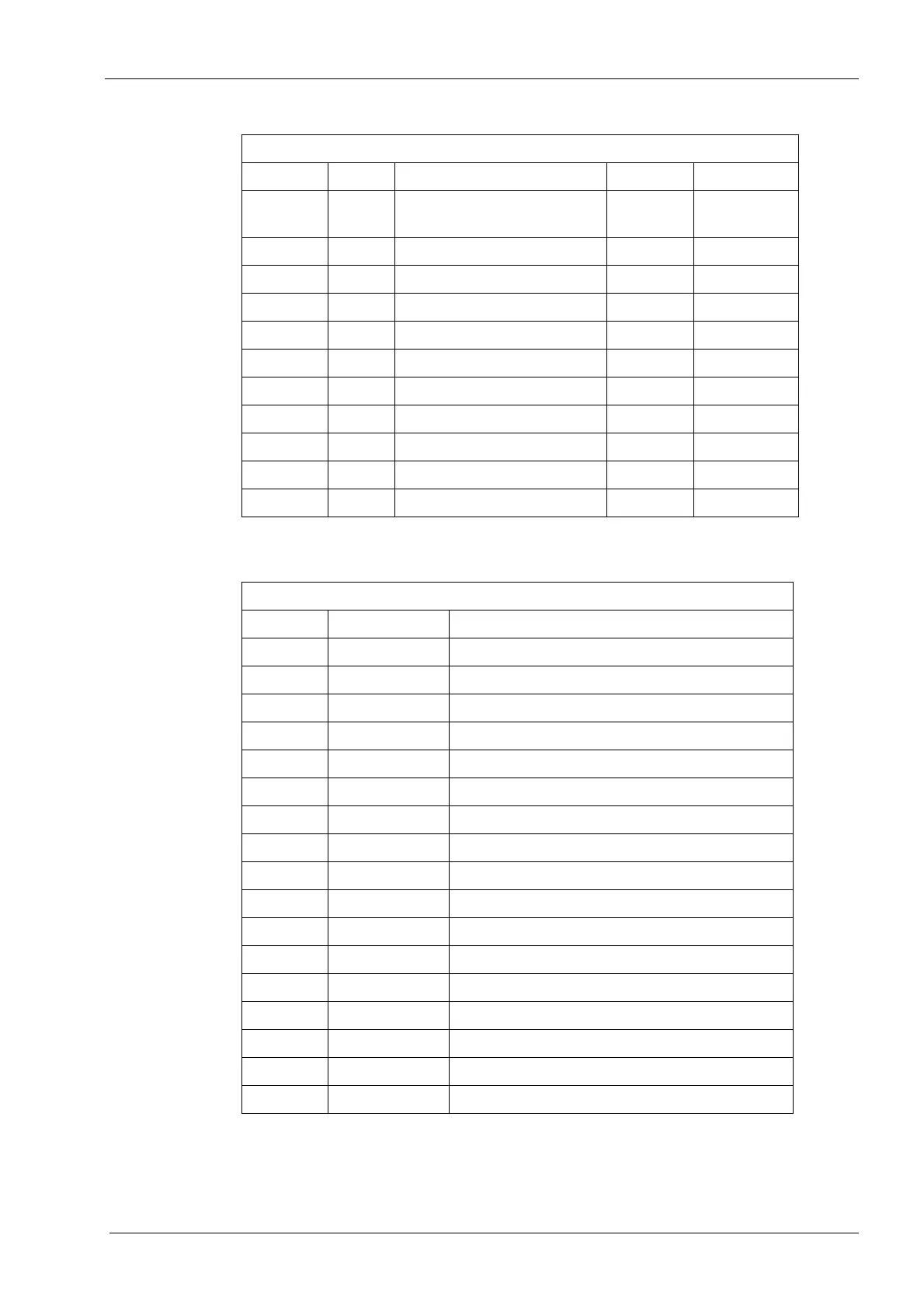
D10 SCS Internal CPU’s
communication
Blink Yellow
D11 CAN CPU-PSU communication Flicker Yellow
D12 RUN CPU Run Blink Yellow
D14 5V Indication On Green
D16 SPI Internal communication On Yellow
D17 RUN I/O CPU Run Blink Yellow
D18 DIS Display communication Flicker Yellow
D19 3V3 ON/OFF Indication On Blue
D20 DIMAX Camera communication Flicker Yellow
D22 LINK Ethernet connection On Green
D23 ACT Ethernet communication Flicker Yellow
Connectors
Reference Name Details
J1 CAMERA Camera communication
J2 PSU PSU power & communication
J3 LINEAR Linear motor control
J4 LIFT Lift motor power
J5 LIFTLIM UP Lift motor up limit
J6 LIFTLIM DOWN Lift motor down limit
J7 STOP Emergency switch
J8 TEMPLEREST Temple rest motor control
J9 LASER Frankfort laser
J10 Backlight connection
J11 Touch panel communication
J13 LCD Hitachi communication
J14 LCD Sharp communication
J20 USB communication
J21 KMK Exp. Switch connection I
J22 KMK Exp. Switch connection II
J23 Ethernet communication
Indicators
Reference Name Details Status Colour
 Loading...


