Cylinder Head and Valves
02
020
27
RG,RG34710,78 –19–13AUG99–1/1
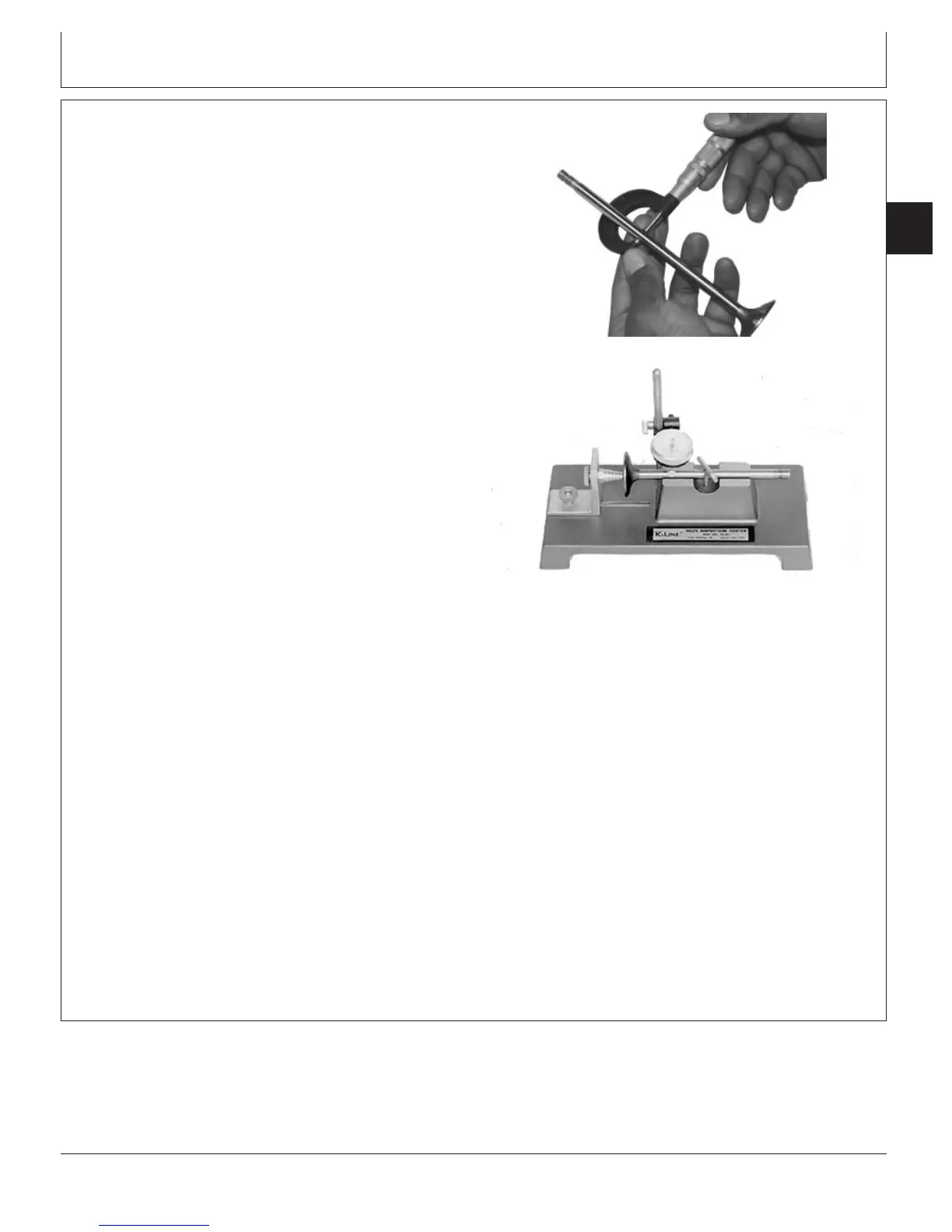
Clean, Inspect, and Measure Valves
RG8322 –UN–21MAY98
Measuring Valve Stem
RG4234 –UN–05DEC97
Measuring Valve Face Runout
1. Hold each valve firmly against a soft brass or copper
wire wheel on a bench grinder.
IMPORTANT: Any carbon left on the stem will affect
alignment in valve refacer. DO NOT use
a wire wheel on plated portion of valve
stem. Polish the valve stem with steel
wool or crocus cloth to remove any
scratch marks left by the wire brush.
2. Make sure all carbon is removed from valve head,
face, and unplated portion of stem.
3. Inspect valve face, stem, tip, and retainer lock groove.
4. Measure valve stem OD Record measurements and
compare with valve guide ID. (See MEASURE VALVE
GUIDE ID, later in this group.)
Specification
Intake and Exhaust Valve
Stems—OD 8.999 ± 0.013 mm (0.3543 ±
0.0005 in.)
...................................................
5. Using a valve inspection center, determine if valves are
out of round, bent, or warped.
Specification
Intake and Exhaust Valve
Face
1
—Maximum Runout 0.038 mm (0.0015 in.).......................................
6. Measure valve head OD.
Specification
Intake and Exhaust Valve Head—
OD 46.35—46.61 mm (1.825—1.835
in.)
.........................................................
1
Maximum runout measured at 44 mm (1.73 in.) diameter.
CTM100 (06APR04)
02-020-27
P
OWER
T
ECH
10.5 L & 12.5 L Diesel Engines
040604
PN=99