Cooling System
02
070
7
RG,RG34710,226 –19–18SEP02–1/2
Replace Belt Tensioner Assembly
RG10270 –UN–30JUL99
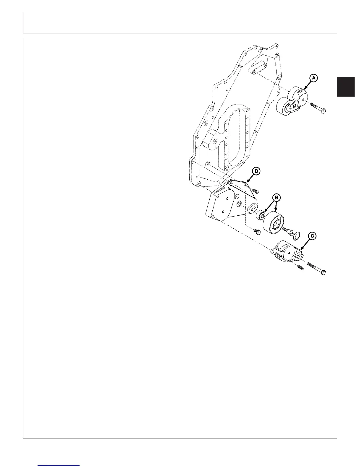
Upper and Lower Belt Tensioners
A—Upper Belt Tensioner
B—Belt Idler Pulley Assembly
C—Lower Belt Tensioner
D—Lower Tensioner Bracket
Follow same procedure for replacement of upper (A) and
lower (C) belt tensioner.
1. Release tension on pulley and remove belt.
2. Check spring tension on tensioner. (See INSPECT
AND CHECK BELT TENSIONER SPRING TENSION
earlier in this group.)
NOTE: Later cam access covers will have two locator
holes for positioning of the upper belt tensioner.
Mark location of hole being used for ease of
installation.
3. Remove cap screw and remove the tensioner
assembly.
NOTE: If cam access cover is equipped with two upper
tensioner locating holes, reinstall upper tensioner
using locating hole previously marked on
disassembly.
Apply LOCTITE
242 Thread Lock and Sealer
(TY9473) to tensioner shoulder bolt or cap screw
before installing.
4. Install tensioner using locator in upper tensioner only
and tighten shoulder bolt or flanged head cap screw to
specifications.
Specification
Belt Tensioner Shoulder Bolt or
Flanged Head Cap Screw—
Torque 50 N•m (37 lb-ft).............................................................................
NOTE: Apply LOCTITE
242 Thread Lock and Sealer
(TY9473) to idler pulley mounting cap screw
before installing.
5. Install idler pulley assembly.
6. Tighten idler pulley (B) cap screw to specifications.
Specification
Fan Belt Idler Pulley—Torque 68 N•m (50 lb-ft).........................................
LOCTITE is a registered trademark of Loctite Corp.
CTM100 (06APR04)
02-070-7
P
OWER
T
ECH
10.5 L & 12.5 L Diesel Engines
040604
PN=291
Continued on next page