Group 120
Base Engine Operation
03
120
1
RG,RG34710,1518 –19–09SEP02–1/3
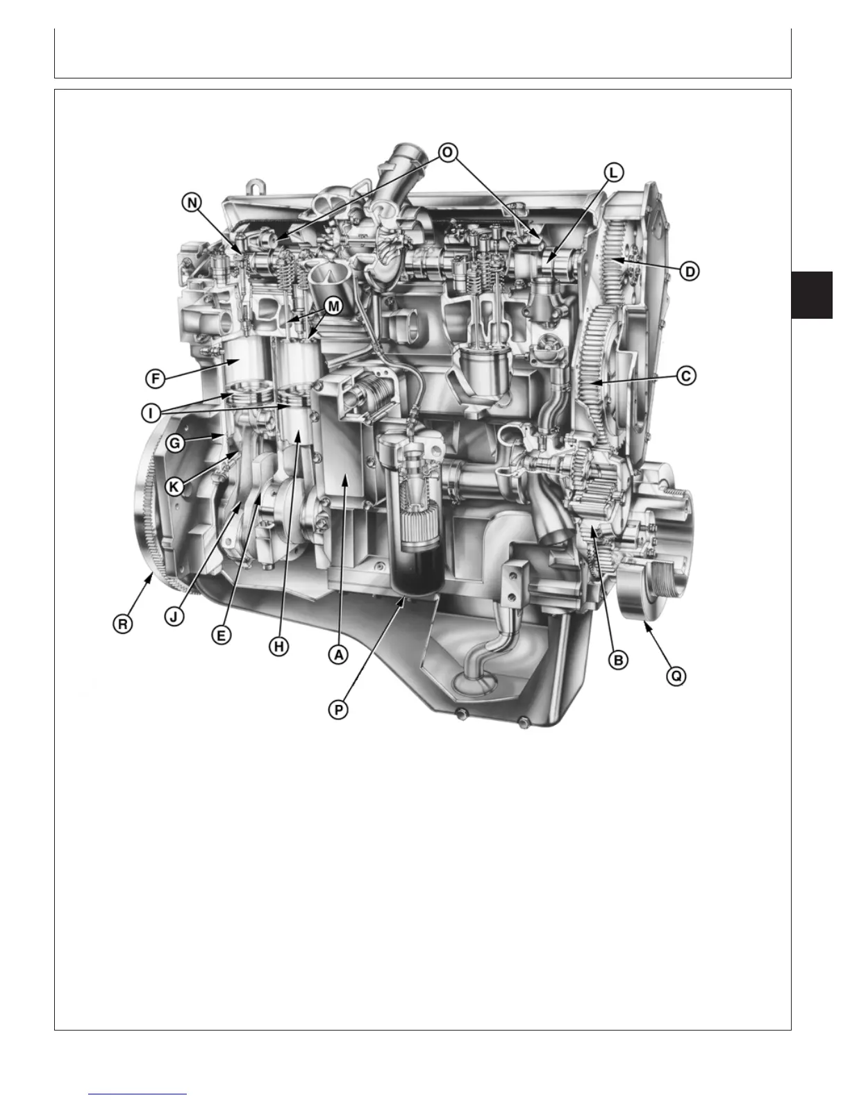
General Engine Operation
RG12419 –UN–11SEP02
Engine Components
A—Oil Cooler F—Cylinder Liner K—Oil Spray Jet P—Oil Filter
B—Oil Pump Drive Gear G—Cylinder Liner O-rings L—Camshaft Q—Crankshaft Damper
C—Idler Gear H—Piston M—Valves R—Flywheel
D—Camshaft Gear I—Piston Rings N—Electronic Unit Injector
E—Crankshaft J—Connecting Rod O—Two-Piece Rocker Arm
Shaft
The 6105 and 6125 engines include a cam in head,
actuating four valves per cylinder and an electronic
unit injector (EUI) fuel system. They are vertical stroke,
in-line, valve-in-head, 6-cylinder diesel engines. The
firing order is 1-5-3-6-2-4.
The cast block has ribbed walls to add strength and
rigidity, and to decrease noise and vibration. The 6105
and 6125 use the same block. The crankshafts and
pistons are different to produce a long stroke and short
stroke engine.
CTM100 (06APR04)
03-120-1
P
OWER
T
ECH
10.5 L & 12.5 L Diesel Engines
040604
PN=333
Continued on next page