Group 100
Starting and Charging Systems
02
100
1
DPSG,OUO1004,1005 –19–23SEP02–1/1
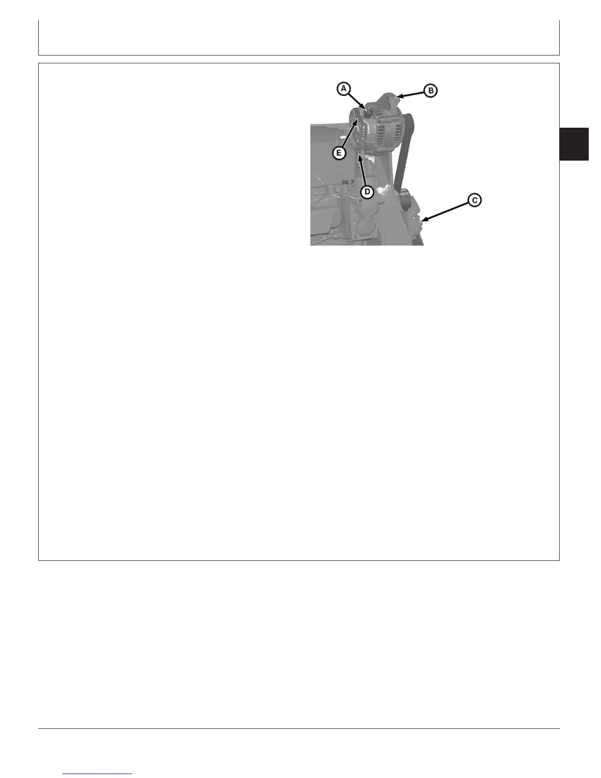
Remove and Install Alternator (OEM Engines)
RG10286 –UN–20AUG99
Alternator
A—Positive Wire Terminal
B—Alternator Strap
C—Belt Tensioner
D—Mounting Cap Screw and Nut
E—Regulator Connector Terminal
IMPORTANT: The alternator is designed with a
Transient Voltage Protector (TVP) to
protect the engine electronics. A regular
alternator without the TVP could cause
extensive damage to the electronics.
NOTE: For test and repair of alternator, refer to CTM 77.
1. Disconnect battery ground (-) cable.
2. Disconnect positive (+) red wire (A) and regulator
connector (E) (shown disconnected).
3. Remove alternator belt using a 1/2 in. drive ratchet on
the belt tensioner (C).
4. Remove mounting cap screws from adjusting strap (B).
Remove cap screw and nut (D) and remove alternator.
5. Install alternator in reverse order.
6. Torque alternator mounting hardware to the following
specifications.
Alternator Strap Mounting Hardware—Specification
M8 Cap Screw—Torque 25 N•m (18 lb-ft)..................................................
M10 Cap Screw—Torque 50 N•m (37 lb-ft)................................................
1/2 in. Cap Screw—Torque 61 N•m (45 lb-ft).............................................
Alternator Foot Mounting Hardware—Specification
M10 Cap Screw—Torque 70 N•m (52 lb-ft)................................................
M12 Cap Screw—Torque 60 N•m (44 lb-ft)................................................
7. Inspect alternator belt for cracks and wear.
CTM100 (06APR04)
02-100-1
P
OWER
T
ECH
10.5 L & 12.5 L Diesel Engines
040604
PN=329