Cylinder Head and Valves
02
020
10
RG,RG34710,64 –19–21DEC00–1/2
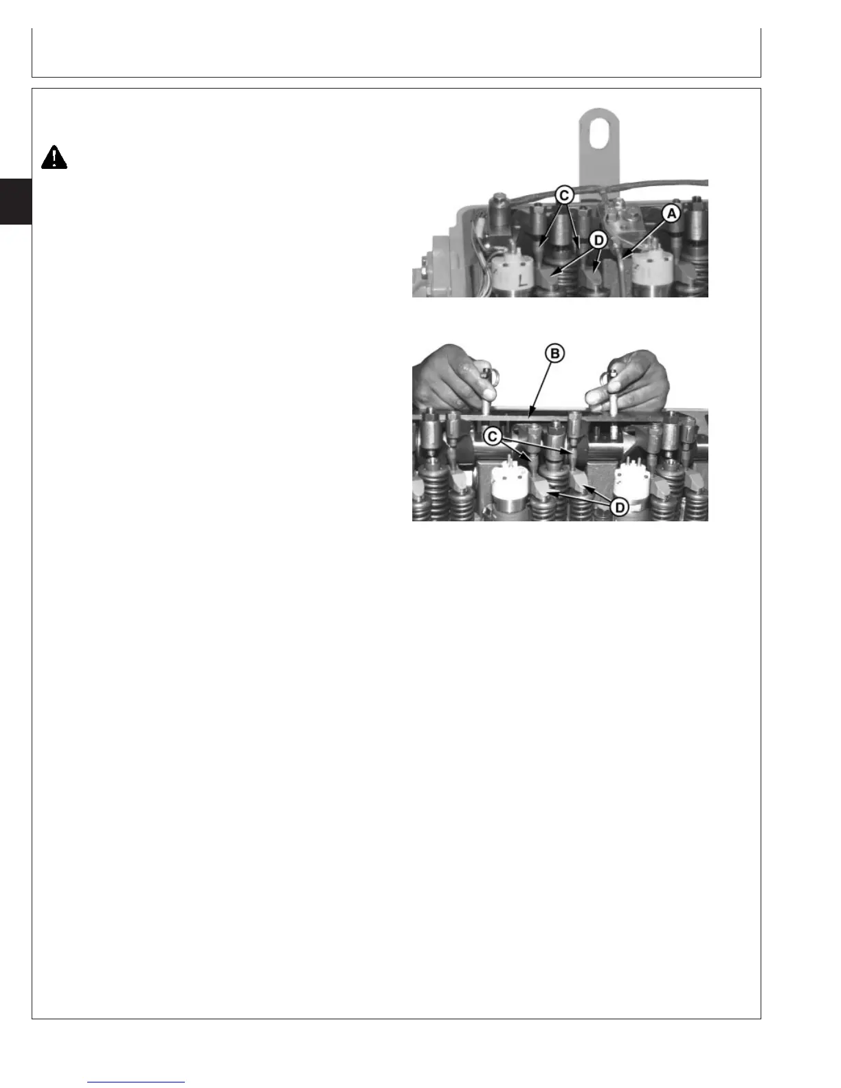
Remove Rocker Arm Assembly
RG8262B –UN–06DEC97
Removing Valve Bridge and Push Tubes
RG8459A –UN–21JUL99
Removing Rocker Arm Assembly with JDG970A
A—Rocker Arm Shaft Oil Tubes (Dual Rail Fuel
System Only)
B—Rocker Arm Lifting Fixture
C—Push Tubes
D—Valve Bridges
CAUTION: After operating engine, allow exhaust
system to cool before servicing engine.
1. Remove rocker arm cover.
2. Lock camshaft and crankshaft at TDC of No.1
cylinder’s compression stroke.
3. Remove electronic unit injector wiring harness from
rocker arm shaft clamps.
IMPORTANT: ALWAYS loosen all intake, exhaust and
EUI rocker arm adjusting screws before
removal or installation of rocker arm
assembly to relieve pressure. This
allows for a more uniform rocker arm
cap screw clamp load and reduces the
possibility of damage to valve train
components.
Remove push tubes and valve bridges
immediately after relieving rocker arm
pressure. Push tubes can fall into oil
drain opening of cylinder head causing
oil pan removal to retrieve tubes.
4. Loosen EUI, intake, and exhaust valve rocker arm
adjusting screw lock nut and relieve pressure at all
locations.
5. Remove push tubes (C) and valve bridges (D) from all
valve stems.
6. Remove two rocker arm shaft oil tubes (A) (dual rail
system only). Remove rocker arm shaft hold-down
clamps.
IMPORTANT: Rocker arm shaft hold-down clamp cap
screws can not be reused. Use new cap
screws for reassembly.
7. Install shaft clamp cap screw in end hole of each
rocker arm shaft so that rocker arms do not slide off
shaft when lifted.
CTM100 (06APR04)
02-020-10
P
OWER
T
ECH
10.5 L & 12.5 L Diesel Engines
040604
PN=82
Continued on next page