Cylinder Block, Liners, Pistons, and Rods
02
030
41
RG,RG34710,128 –19–03AUG99–1/2
Measure Cylinder Block
RG8208 –UN–21MAY98
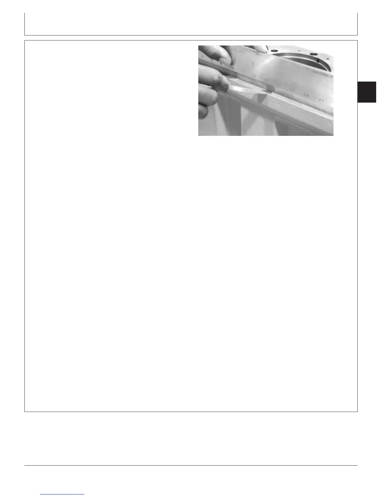
Measuring Block Top Deck Flatness
Refer to the appropriate groups for a more detailed
description of the features being measured. Compare
measurements with specifications given below.
1. Assemble and measure main and thrust bearing bores.
Compare measurements with specifications given
below:
Specification
Main and Thrust Bearings—
Assembled ID Without Bearings 133.097—133.123 mm
(5.2400—5.2410 in.)
...........................
Main Bearing Surface Width 37.77—38.03 mm (1.487—1.497
in.)
.................
Thrust Bearing Surface Width
(No. 5 Main) 37.51—38.29 mm (1.476—1.507
in.)
..........................................
Overall Thrust Bearing Cap Width 43.25—43.75 mm (1.703—1.722
in.)
........
If any main or thrust bearing cap assembled ID is not
within specification, blank (generic) bearing caps are
available and must be line bored to specification by a
qualified machine shop. (See MEASURE ASSEMBLED ID
OF MAIN BEARING CAPS in Group 040.)
2. Measure cylinder block top deck flatness using
D05012ST Precision Straightedge and feeler gauge.
Resurface as required.
Specification
Cylinder Block Top Deck Surface
Finish—Surface Finish (Surface
Mill Only) 3.2 micrometers (125 micro-in.)...................................................
Max. Wave Height 0.008 micrometers (0.0002
micro-in.)
...........................................
Max. Wave Depth 2.0 micrometers (79 micro-in.).......................................
Main Bearing Bore
Centerline-to-Top Deck—
Minimum Distance 429.92—430.07 mm
(16.926—16.932 in.)
.....................................................
Continued on next page
CTM100 (06APR04)
02-030-41
P
OWER
T
ECH
10.5 L & 12.5 L Diesel Engines
040604
PN=181