Cylinder Head and Valves
02
020
2
RG,RG34710,60 –19–03NOV99–2/2
Specification
Rocker Arm Cover Hold-Down
Cap Screws
1
—Torque 30 N•m (22 lb-ft).....................................................
5. Install air intake cross-over tube and tighten
connections securely.
1
Tighten center cap screw first, then tighten sides.
RG,RG34710,61 –19–03SEP02–1/1
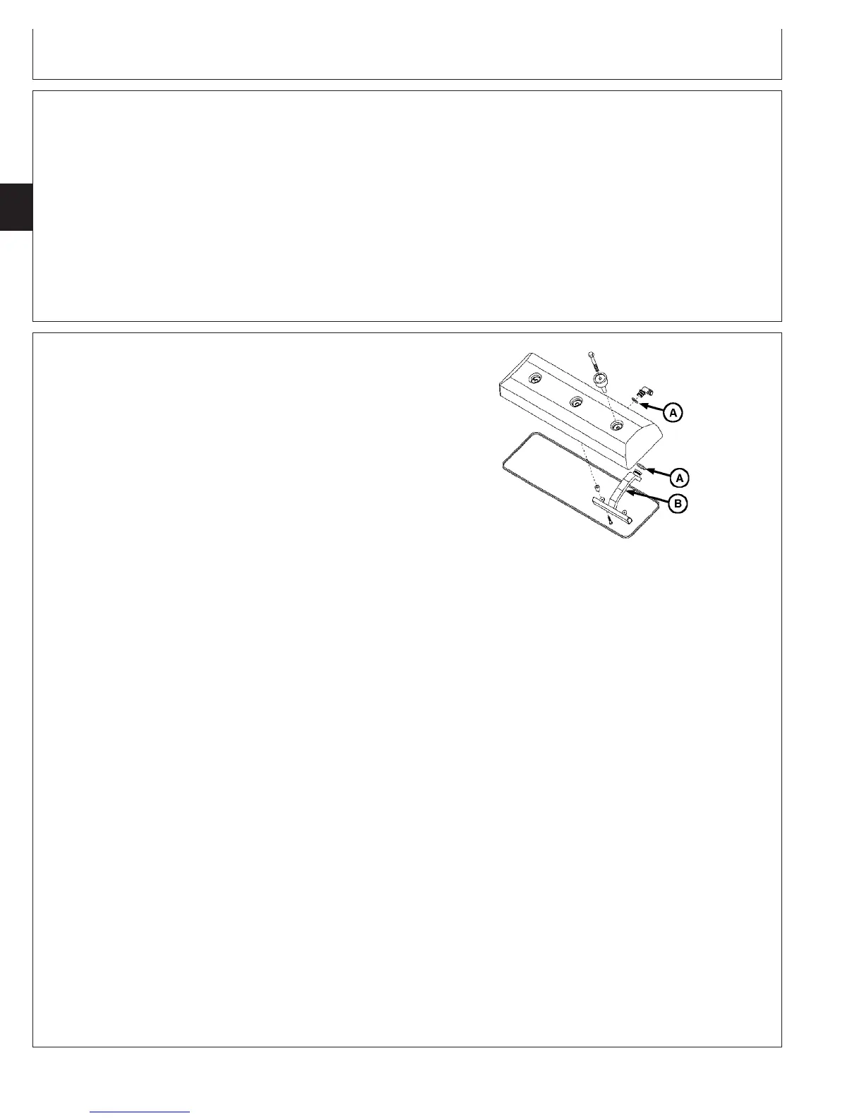
Clean and Inspect Crankcase Ventilation
Assembly
RG10242 –UN–20JUL99
Crankcase Ventilation Assembly
A—O-Rings
B—Ventilator Assembly
1. Remove ventilation outlet tube from rocker arm cover
(shown removed).
NOTE: Ventilator assembly-to-rocker cover self-tapping
cap screws have been replaced by flange head
cap screws with pre-applied sealant. Discard old
self-tapping cap screws and replace with new cap
screws.
2. Remove two cap screws securing ventilator assembly
(B) to cover and remove.
3. Clean ventilator assembly in solvent and dry with
compressed air.
4. Install ventilator assembly in reverse order of removal.
Replace O-rings (A) as necessary.
5. Tighten ventilator assembly-to-rocker arm cover cap
screws to specifications.
Specification
Crankcase Vent Baffle-to-Rocker
Arm Cover Cap Screws—Torque 15 N•m (11 lb-ft) (133 lb-in.).................
6. Install ventilator outlet tube onto elbow attached to
rocker arm cover.
CTM100 (06APR04)
02-020-2
P
OWER
T
ECH
10.5 L & 12.5 L Diesel Engines
040604
PN=74