Camshaft and Timing Gear Train
02
050
18
DPSG,OUO1004,1021 –19–08SEP99–1/1
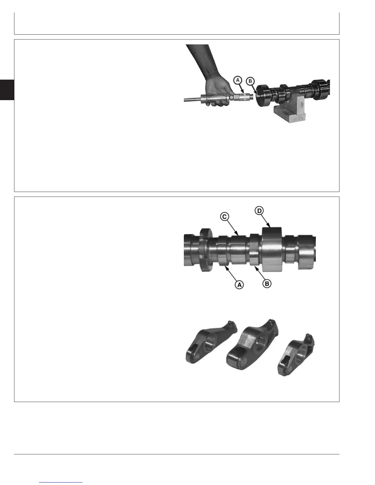
Replace Fuel Supply Pump Drive Pin
RG10344 –UN–09SEP99
Fuel Supply Pump Drive Pin
A—Dowel Pin Puller
B—Fuel Supply Pump Drive Pin
1. Remove camshaft. (See REMOVE AND INSTALL
CAMSHAFT earlier in this group.)
2. Remove fuel supply pump drive pin (B) using Snap-On
CG503 Dowel Pin Puller Set (A) or equivalent tool.
3. Press new drive pin into end of camshaft until it
bottoms out. Pin should protrude 15.45—17.45 mm
(0.608—0.687 in.) from end of camshaft.
4. Install camshaft. (See REMOVE AND INSTALL
CAMSHAFT earlier in this group.)
RG,RG34710,192 –19–30SEP97–1/1
Visually Inspect Camshaft and Roller
Followers
RG8385B –UN–09DEC97
Inspecting Camshaft Lobes
RG8388 –UN–21MAY98
Inspecting Roller Followers
A—Intake Lobe
B—Exhaust Lobe
C—Unit Injector Lobe
D—Bushing Journal
1. Clean camshaft in solvent. Dry with compressed air.
IMPORTANT: Very light score marks may be found on
eccentric lobes, but are acceptable if
valve lift is within specification. Pitting
and galling dictates replacement.
2. Inspect all camshaft eccentric lobes and bushing
journals (D) for wear or damage.
3. Inspect all corresponding rocker arm roller followers for
uneven wear or damage.
Replace individual roller followers as necessary.
CTM100 (06APR04)
02-050-18
P
OWER
T
ECH
10.5 L & 12.5 L Diesel Engines
040604
PN=258