Crankshaft, Main Bearings, and Flywheel
02
040
6
RG,RG34710,153 –19–12SEP02–1/1
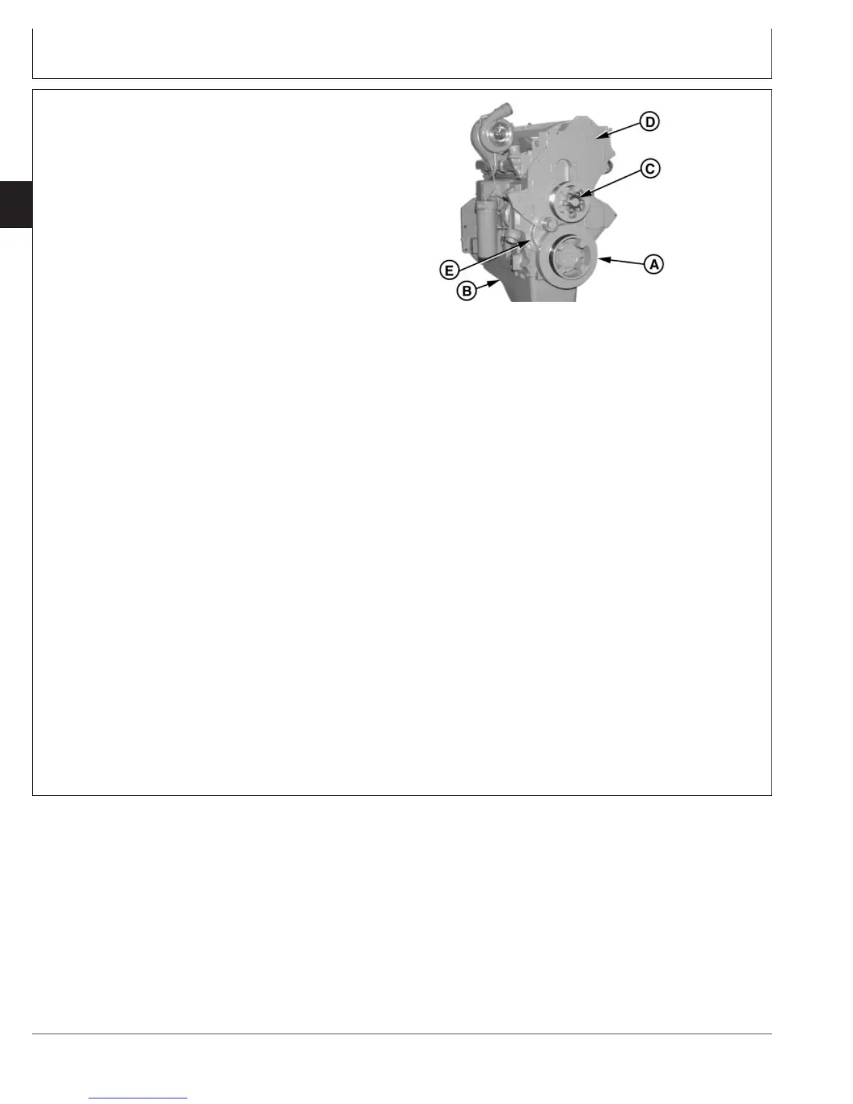
Remove Timing Gear Cover
RG8178 –UN–05DEC97
Removing Timing Gear Cover
A—Vibration Damper
B—Oil Pan
C—Fan Drive Assembly
D—Camshaft Gear Access Cover
E—Timing Gear Cover
1. If not previously done, remove vibration damper and
pulley (A). (See REMOVE CRANKSHAFT VIBRATION
DAMPER AND PULLEY, earlier in this group.)
2. Drain engine oil if not previously done and remove
engine oil pan (B). (See REMOVE ENGINE OIL PAN
in Group 060.)
3. Disconnect crankshaft position sensor.
NOTE: On engines with fixed fan drive assembly, the fan
drive housing is cast into the camshaft gear
access cover.
4. Remove fan drive assembly (C). (See REPLACE
BEARINGS IN FAN DRIVE ASSEMBLY in Group 070.)
NOTE: Mark location of cap screws to aid in reassembly.
5. Remove camshaft gear access cover (D) from timing
gear cover. Mark location of cap screws to aid in
reassembly.
6. Remove remaining cap screws and remove timing gear
cover. Mark location of cap screws to aid in
reassembly.
NOTE: On engines with fixed fan drive, the lower right
cap screw (under pulley) will have to be
reinstalled in camshaft gear access cover bore
prior to installing pulley. Once pulley is installed, it
interferes with the installation of this cap screw.
CTM100 (06APR04)
02-040-6
P
OWER
T
ECH
10.5 L & 12.5 L Diesel Engines
040604
PN=202