Lubrication System
02
060
13
RG,RG34710,216 –19–24SEP02–2/2
RG12611 –UN–30AUG02
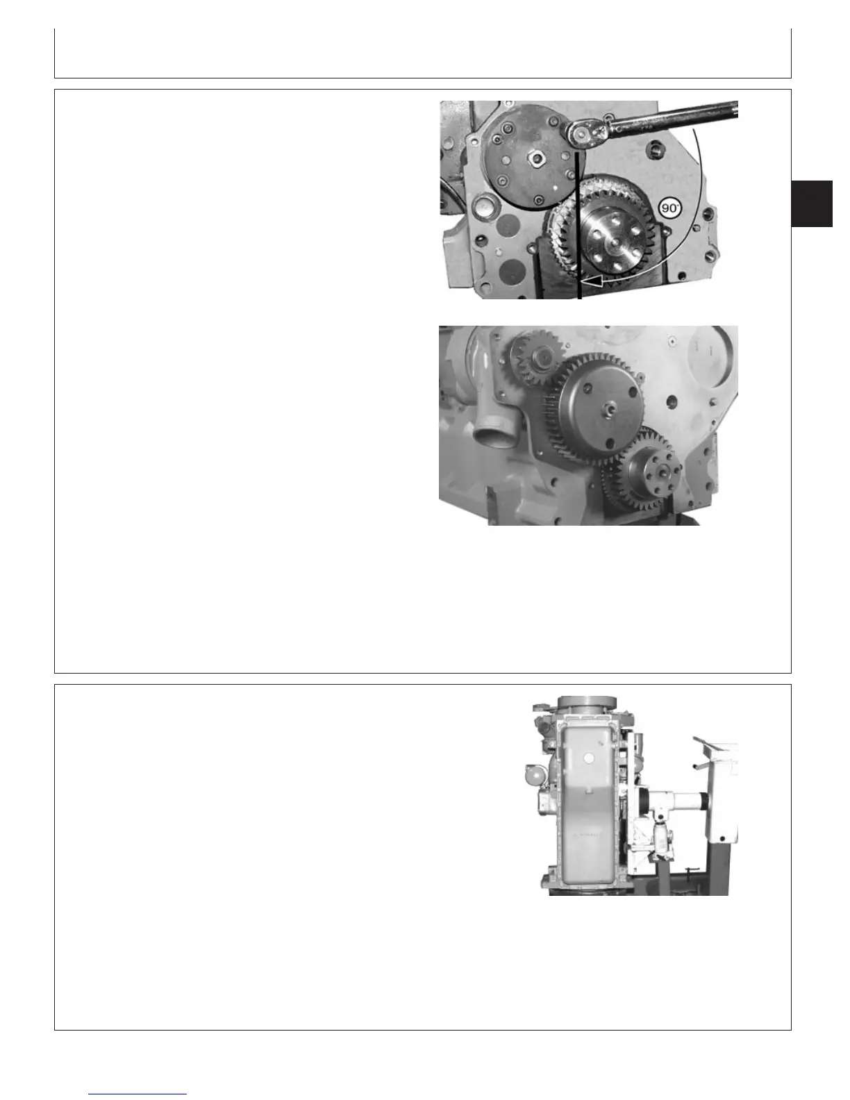
90
°
Torque Turn
RG8256 –UN–21MAY98
Installing Oil Pump Drive Gear
4. Second: Starting with first cap screw tightened, apply
90° torque turn to each cap screw.
Specification
Oil Pump-to-Block Cap Screws—
Torque Turn 90° (1/4 Turn)..........................................................................
5. Rotate input shaft full 360° after pump installation. If
shaft does not turn freely for full 360°, remove pump
and determine cause.
6. Apply TY6333 or TY6347 High Temperature Grease to
ID of oil pump drive gear bushing.
7. Install oil pump gear with bushing over oil pump
housing; align input shaft with opening in gear.
8. Install external snap ring in groove of input shaft.
9. Check oil pump drive gear-to-idler gear backlash.
Specification
Oil Pump Drive Gear-to-Idler
Gear—Backlash 0.25 mm (0.010 in.)..........................................................
10. Install timing gear train cover and complete final
assembly. (See INSTALL TIMING GEAR COVER in
Group 040.)
RG,RG34710,217 –19–30SEP97–1/1
Remove Engine Oil Pan
RG8819 –UN–20MAY98
Removing Oil Pan
1. Disconnect turbocharger oil inlet line. Remove oil pan
drain plug and drain all engine oil.
NOTE: It may be necessary to tap oil pan with a rubber
or plastic dead-blow hammer to free oil pan from
gasket seal.
2. Remove all 30 oil pan cap screws and remove oil pan
from cylinder block.
3. Remove all gasket material from oil pan and cylinder
block gasket sealing surfaces.
4. Clean all oil from oil pan and cylinder block sealing
surfaces and dry completely.
CTM100 (06APR04)
02-060-13
P
OWER
T
ECH
10.5 L & 12.5 L Diesel Engines
040604
PN=281