Cylinder Head and Valves
02
020
56
RG,RG34710,94 –19–30SEP97–1/1
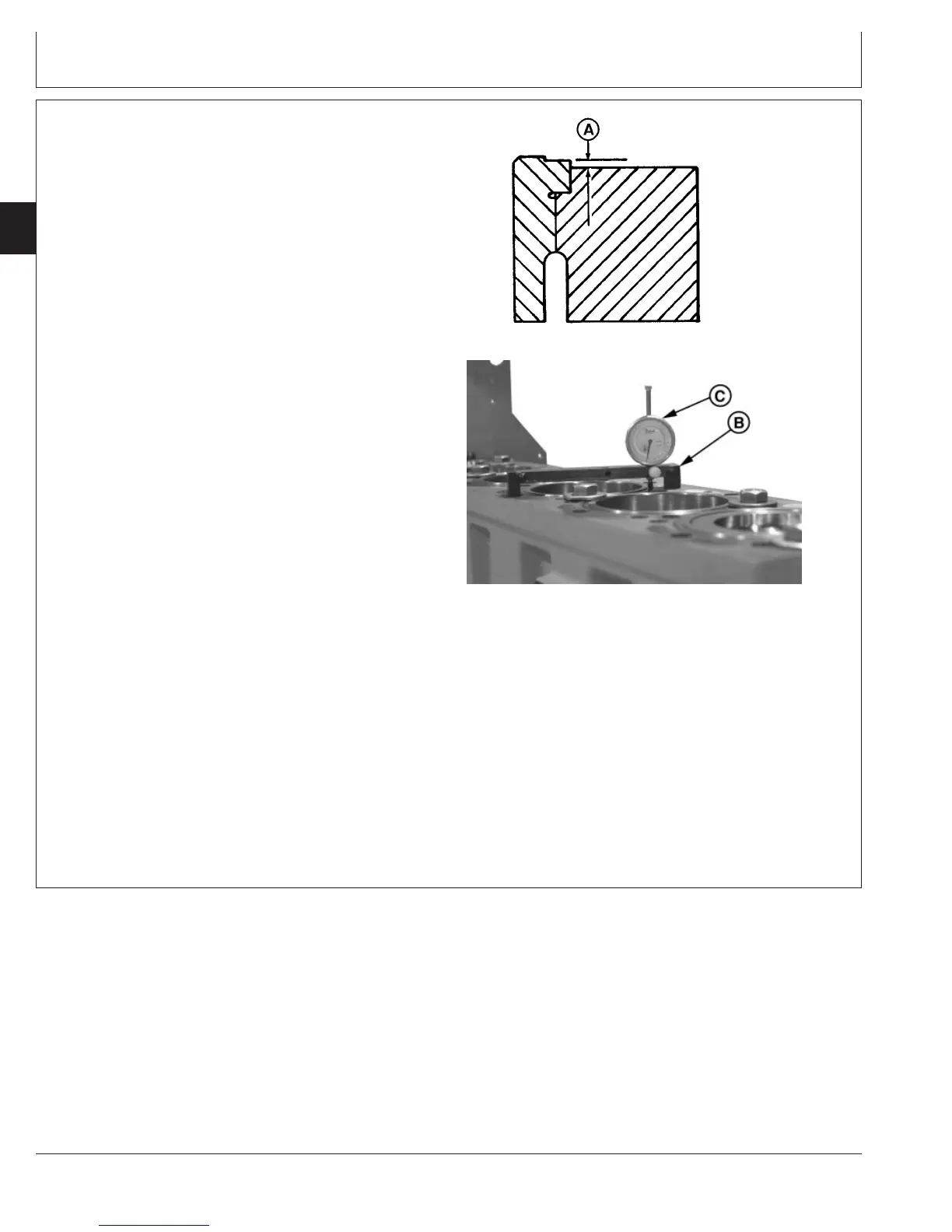
Measure Cylinder Liner Standout (Height
Above Block)
RG6439 –UN–03NOV97
Liner Standout
RG8329A –UN–06DEC97
Measuring Liner Standout
A—Liner Height
B—Height Gauge
C—Dial Indicator
1. Secure liners using cap screws and flat washers. Flat
washers should be at least 3.18 mm (1/8 in.) thick.
Tighten cap screws to 68 N•m (50 lb-ft).
2. Using JDG451 or KJD10123 Height Gauge (B) and
D17526CI or D17527CI Dial Indicator (C), measure
liner height (A) at approximately 1, 5, 7, and 11 o’clock
positions as viewed from flywheel end of engine.
Record all measurements by cylinder number.
Specification
Cylinder Liner—Height Above
Block (Standout) 0.030—0.117 mm
(0.0012—0.0046 in.)
............................................................
Cylinder Liner—Max. Height
Difference at Nearest Point of
Two Adjacent Liners or Within
One Liner 0.051 mm (0.0020 in.)................................................................
IMPORTANT: ONE LINER SHIM ONLY may be
installed under any given liner flange.
3. Remove liner, add shims or replace any liner that does
not fall within allowable standout specification.
Two sizes of shims are available:
R81276 ................................................................... 0.05 mm (0.002 in.)
R87277 ................................................................... 0.10 mm (0.004 in.)
CTM100 (06APR04)
02-020-56
P
OWER
T
ECH
10.5 L & 12.5 L Diesel Engines
040604
PN=128