Cylinder Block, Liners, Pistons, and Rods
02
030
11
RG,RG34710,108 –19–13AUG99–1/2
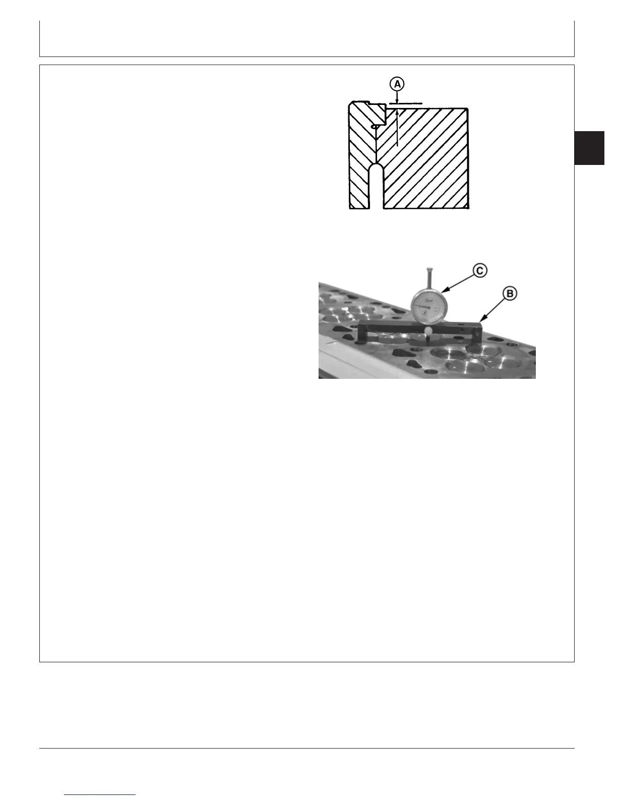
Measure Cylinder Liner Standout (Height
Above Block)
RG6439 –UN–03NOV97
Liner Standout
RG8330B –UN–09DEC97
Measuring Liner Standout
A—Liner Height
B—JDG451 Gauge
C—KJD10123 Gauge
IMPORTANT: Remove all gasket material, rust, carbon
and other foreign material from top
deck of cylinder block. Use compressed
air to remove all loose foreign material
from cylinders and top deck.
NOTE: Liners having obvious defects must be replaced
as a matched piston and liner set.
1. Bolt liners down in seven locations using cap screws
and washers. (See REMOVE PISTONS AND
CONNECTING RODS, earlier in this group.) Tighten
cap screws to 68 N•m (50 lb-ft).
Specification
Cylinder Liner Cap Screws (For
Checking Liner Standout)—
Torque 68 N•m (50 lb-ft).............................................................................
2. Using JDG451 Gauge (B) along with D17526CI
(English scale) or D17527CI (metric scale) Dial
Indicator or KJD10123 Gauge (C), measure liner height
(A) for all cylinders.
3. Measure each liner in four places at approximately 1,
5, 7, and 11 o’clock positions as viewed from rear of
engine (flywheel end). Record all measurements by
cylinder number.
NOTE: Variations in measurement readings may occur
within one cylinder and/or between adjacent
cylinders.
4. If liner standout is below specification, measure liner
flange thickness. (See MEASURE LINER FLANGE
THICKNESS later in this group.) Measure liner
counterbore depth in cylnder block. (See INSPECT
AND CLEAN CYLINDER BLOCK, later in this group.)
Continued on next page
CTM100 (06APR04)
02-030-11
P
OWER
T
ECH
10.5 L & 12.5 L Diesel Engines
040604
PN=151