Cylinder Head and Valves
02
020
9
RG,RG34710,63 –19–16OCT00–6/6
RG9743 –UN–04DEC98
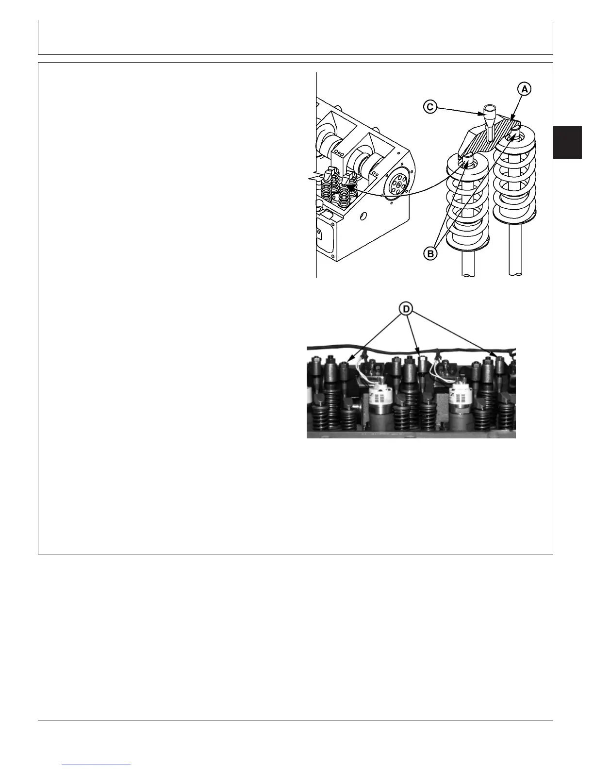
Inspect Valves
RG9626A –UN–04DEC98
Adjusting Screws
A—Valve Bridges
B—Valve Stems
C—Push Tubes
D—Adjusting Screws
IMPORTANT: Thoroughly inspect ALL intake and
exhaust valve bridges (A) for proper
seating on valve stems (B) from both
sides of engine. Also, be sure that push
tubes (C) are properly seated in top of
valve bridge.
Use a flashlight and carefully check
each bridge (for proper seating on valve
stems) from both sides of the engine,
by lifting up on each bridge to verify
proper seating. VALVE BRIDGES THAT
ARE NOT PROPERLY SEATED ON
VALVE STEMS WILL RESULT IN
MAJOR ENGINE VALVE TRAIN
FAILURE.
13. Check that all intake rocker arm adjusting screws (D)
have approximately the same number of threads
visible above lock nut. Normally flush to maximum of
two threads.
If the number of threads above lock nut at any
location is visually different, verify bridge seating and
readjust valve clearance to ensure everything is within
specification at this location.
14. Install plug in timing pin hole below oil cooler and
tighten to specifications.
Specification
Timing Pin Plug (Below Oil
Cooler)—Torque 33 N•m (24 lb-ft)..............................................................
CTM100 (06APR04)
02-020-9
P
OWER
T
ECH
10.5 L & 12.5 L Diesel Engines
040604
PN=81