Cylinder Head and Valves
02
020
8
RG,RG34710,63 –19–16OCT00–5/6
RG8774 –UN–19MAY98
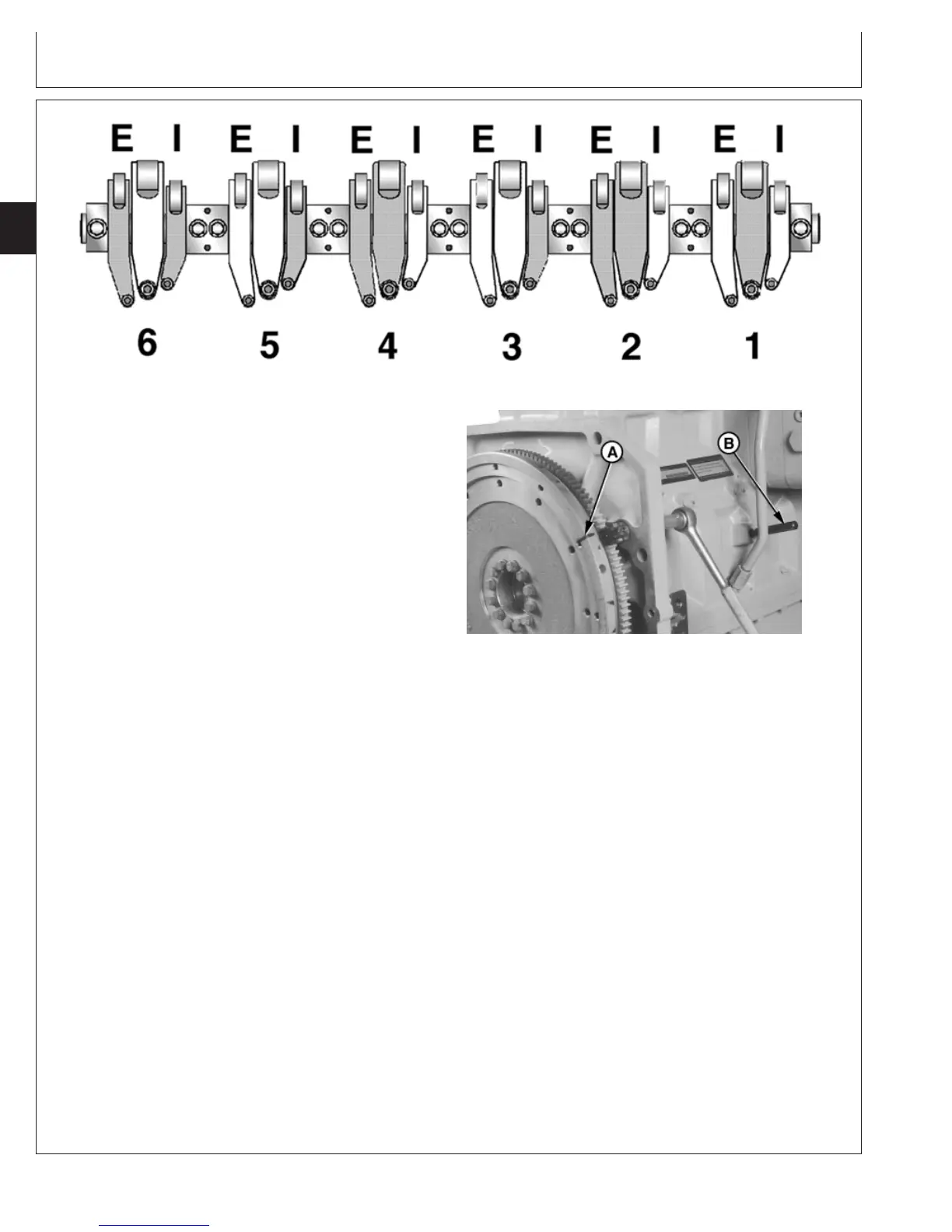
Rocker Arm Assembly Identification
RG8229 –UN–05DEC97
Locking Engine at No.6 TDC
A—Flywheel Reference Mark
B—Timing Pin
9. Reference mark flywheel (A) as shown with engine
locked at No.1 TDC compression stroke.
IMPORTANT: DO NOT insert timing pin full depth into
cylinder block when rotating engine
flywheel until reference mark is within a
few degrees of a full crankshaft
revolution to eliminate possibility of
crankshaft counterweight bending
timing pin.
10. Remove both timing pins and rotate engine flywheel
one full revolution (360°) until timing pin (B) enters
slot in crankshaft again. Engine will now be locked at
No. 6 TDC compression stroke.
11. Check and adjust, as needed, valve clearance (lash)
on intake valves Nos. 3, 5, and 6 and exhaust valves
Nos. 2, 4, and 6 (shaded locations). Adjust preload
on injectors Nos. 1, 2, and 4 (shaded locations).
12. Tighten intake and exhaust valve adjusting screw lock
nuts to specifications.
Specification
Intake and Exhaust Valve
Adjusting Screw Lock Nuts—
Torque 50 N•m (37 lb-ft).............................................................................
Tighten EUI adjusting screw lock nuts to specifications.
Specification
Electronic Unit Injector Adjusting
Screw Lock Nuts—Torque 65 N•m (48 lb-ft)..............................................
CTM100 (06APR04)
02-020-8
P
OWER
T
ECH
10.5 L & 12.5 L Diesel Engines
040604
PN=80
Continued on next page