Camshaft and Timing Gear Train
02
050
5
RG,RG34710,190 –19–19SEP02–2/6
At this location the keyway in crankshaft drive gear will
be at the 12 o’clock position, visible when vibration
damper is removed. This is TDC of No. 1 cylinder’s
compression stroke. Also, with timing pin installed in
camshaft and crankshaft slots, this ensures that
camshaft-to-crankshaft timing is within specification.
RG,RG34710,190 –19–19SEP02–3/6
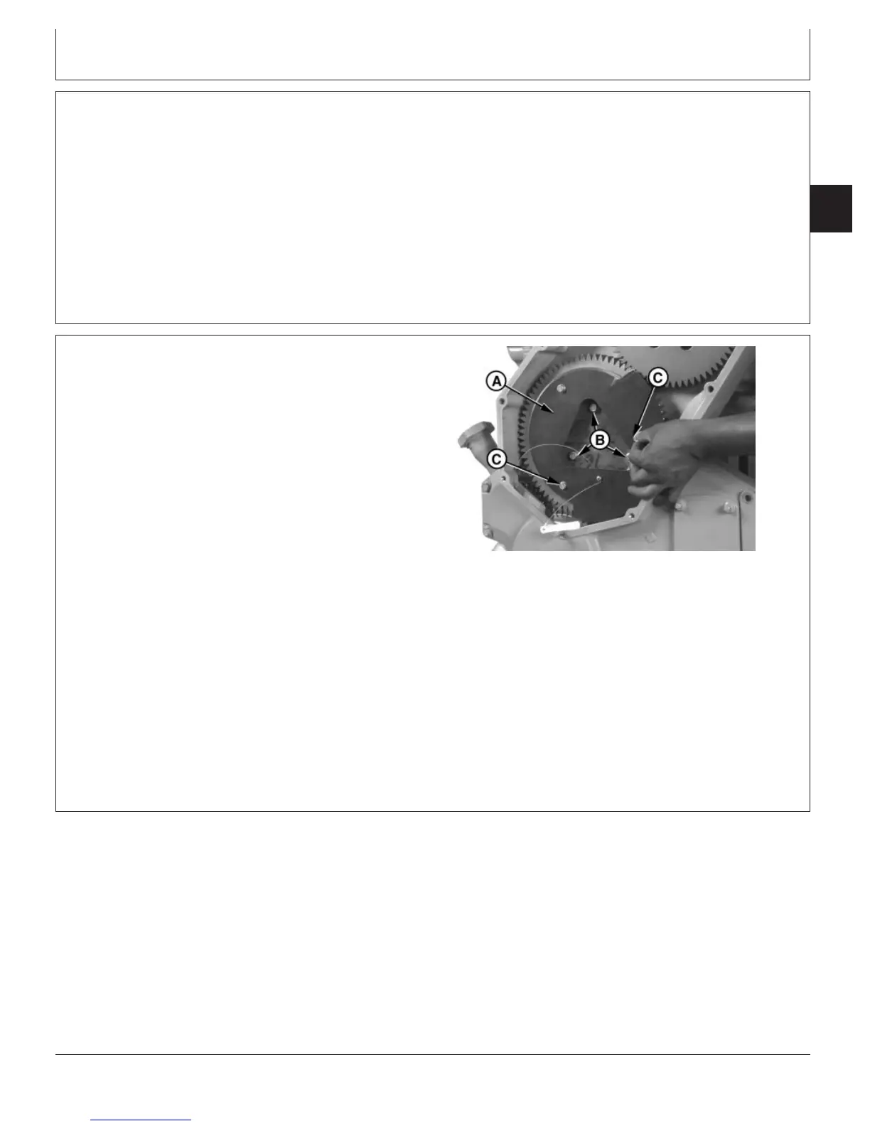
RG8237 –UN–05DEC97
Installing JDG993 Backlash Template
A—JDG993 Timing Gear Backlash Template
B—Upper Idler Gear Bearing Carrier Cap Screws
C—Lower Cap Screws
5. Loosen all six camshaft gear retainer cap screws.
6. Loosen three upper idler gear bearing carrier cap
screws (B), so that carrier can be moved by hand. Do
not loosen more than required for ease of assembly.
NOTE: Upper hole on template is larger and fits over
upper cap screw. This ensures proper placement
of template when installed.
7. Remove two lower cap screws (C) from upper idler
gear thrust plate and install JDG993 Timing Gear
Backlash Template (A) as shown. Re-install two lower
cap screws through template and tighten to
specification.
Specification
Upper Idler Gear Thrust Plate
Cap Screws—Initial Torque 35 N•m (26 lb-ft).............................................
Continued on next page
CTM100 (06APR04)
02-050-5
P
OWER
T
ECH
10.5 L & 12.5 L Diesel Engines
040604
PN=245