© Precor Incorporated, Unauthorized Reproduction and Distribution Prohibited by Law Page 212
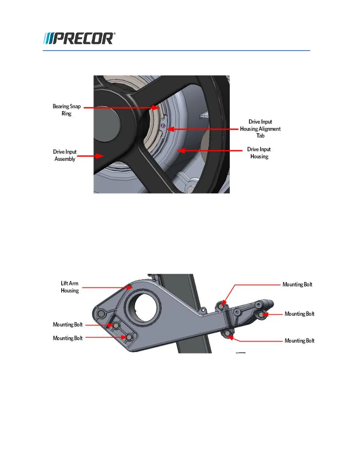
FIGURE 207: DRIVE INPUT ASSEMBLY ALIGNMENT
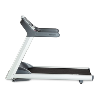
22 Assemble the left and right side arm housings on the drive input housing and secure with the five 5/16-
18X1 mounting bolts.
FIGURE 208: LIFT ARM MOUNTING BOLTS
23 Install the drive input assembly by aligning the bearing snap ring opening with tab of the drive input
housing.
24 Fasten the drive input assembly to the drive input housing using the screw and square washer. Make
sure that the square washer does not contact the drive input pulley after installation, test by spinning
the drive input pulley through its full range.