© Precor Incorporated, Unauthorized Reproduction and Distribution Prohibited by Law Page 213
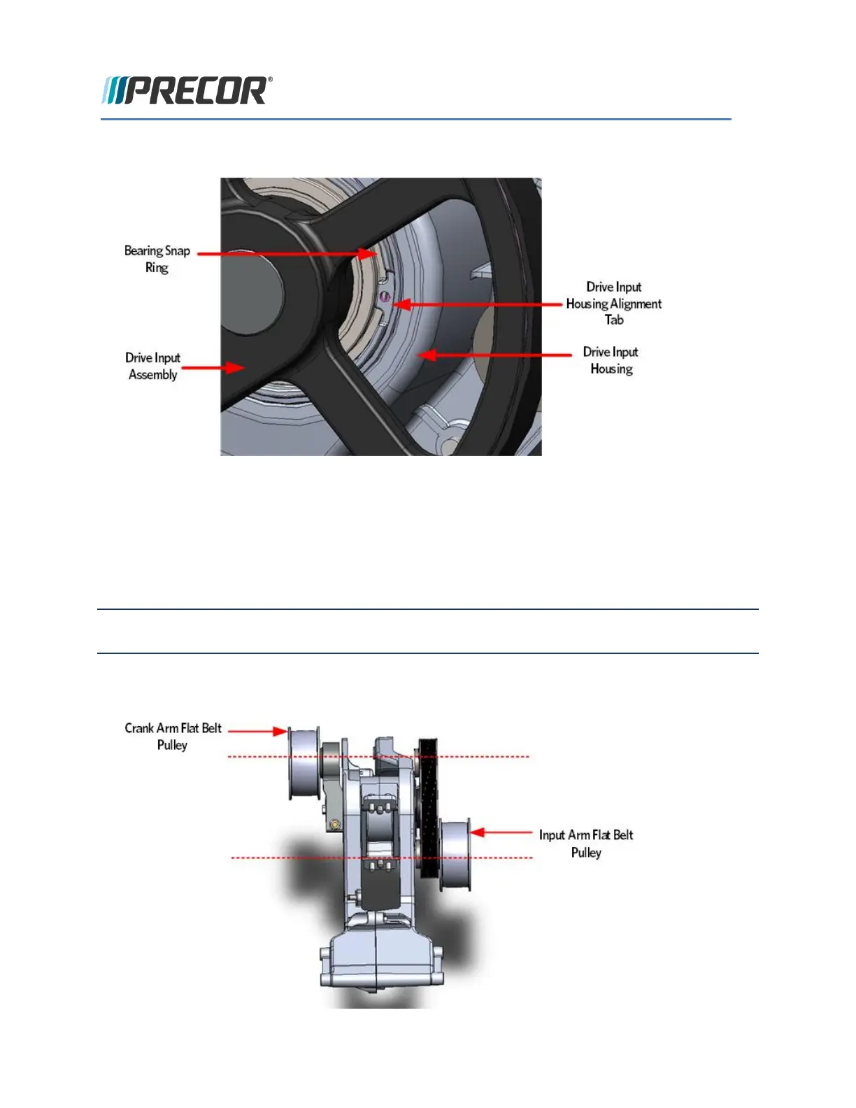
FIGURE 209: DRIVE INPUT ASSEMBLY ALIGNMENT
25 Replace the drive input belt over the drive input pulley and the step up pulley.
26 Place the crank arm on the shaft and secure the crank arm with mounting bolt and washer. To tighten
the crank arm mounting bolt, insert a socket extension about twelve inches long or equivalent in the
drive input housing cavity, just below the crank arm to prevent rotation Remove the crank arm bolt,
washer and crank arm. Torque the mounting bolt to 300 inch pounds or 25 foot pounds.
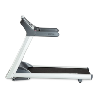
Note The position of the flat belt pulley on the crank arm and the flat belt pulley on the input pulley. When
the crank arm is replaced, the flat belt pulleys must be positioned so that they are 180 degrees opposing.
FIGURE 210: CRANK ARM ALIGNMENT