© Precor Incorporated, Unauthorized Reproduction and Distribution Prohibited by Law Page 231
9 Secure the cam assembly to the frame using the bolt and washer, torque the bolt to 480 inch pounds.
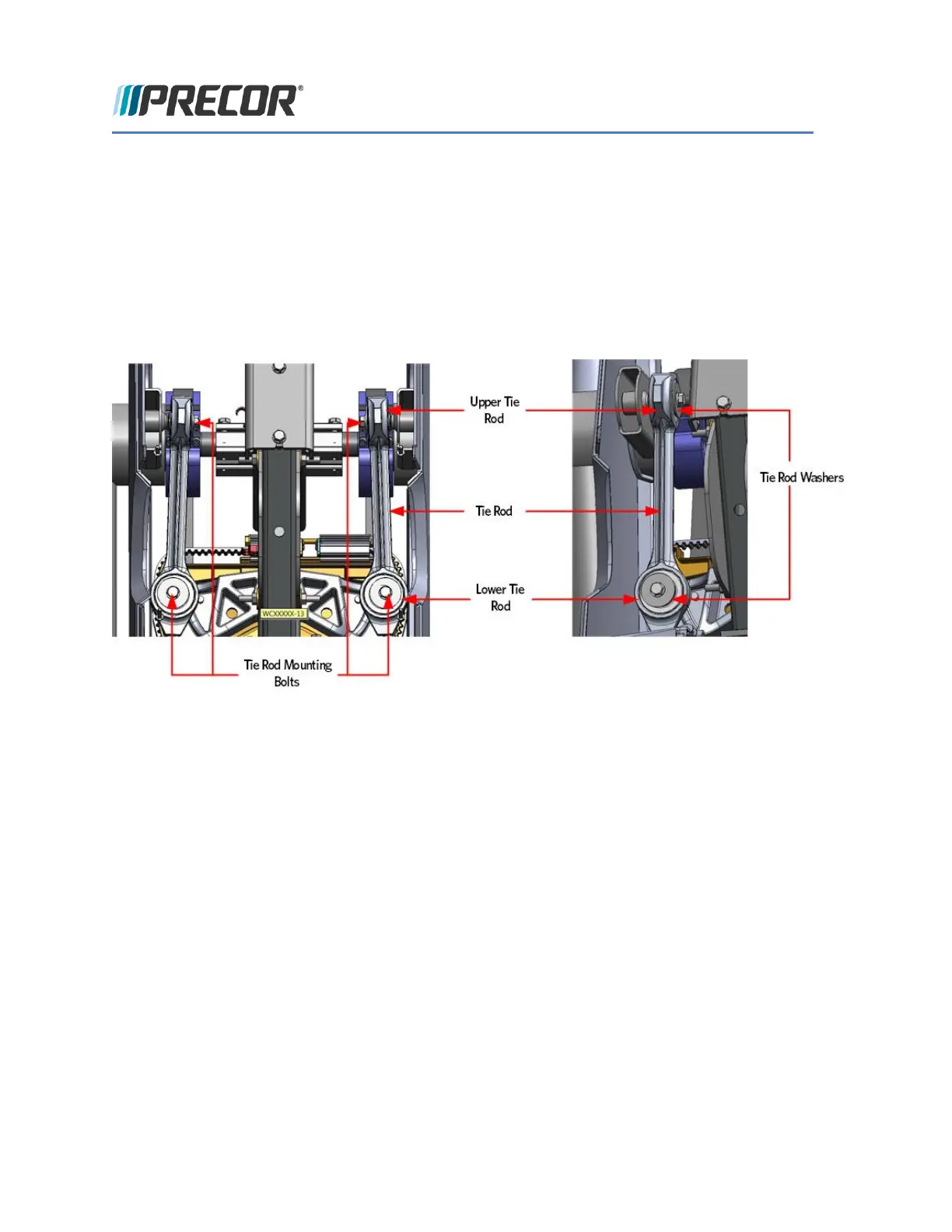
Tie Rod Installation
10 Fasten each lower tie rod end to the cam assembly using the bolts and washers, torque the bolt to 300
inch pounds.
FIGURE 231: TIE RODS
Stride Dial Assembly Installation
11 Secure the stride dial assembly to the frame with the two screws, do not fully tighten the screws.
12 Adjust the stride dial bracket unit the stride dial target is centered between the two stride sensors on the
stride dial PCA.
13 Fully tight in the two screws that secure the stride dial sensor to the frame.
14 Reconnect the stride dial cable connector to the stride dial sensor, ensure the cable is routed and
secured away from the H-Brake cam stops.