Section 3 Exception Handling
Rev. 7.00 Mar 10, 2005 page 76 of 652
REJ09B0042-0700
When system power is turned on or off, the
RES
pin should be held low.
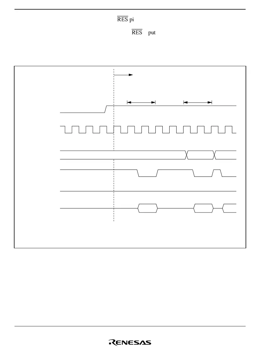
Figure 3.1 shows the reset sequence starting from
RES
input.
See section 14.3.1, Power-On Reset Circuit, for information on the reset sequence for the
H8/38124 Group, which is equipped with an on-chip power-on reset circuit.
Vector fetch
φ
Internal
address bus
Internal read
signal
Internal write
signal
Internal data
bus (16-bit)
RES
Internal
processing
Program initial
instruction prefetch
(1) Reset exception handling vector address (H'0000)
(2) Program start address
(3) First instruction of program
(2) (3)
(2)
(1)
Reset cleared
Figure 3.1 Reset Sequence
3.2.3 Interrupt Immediately after Reset
After a reset, if an interrupt were to be accepted before the stack pointer (SP: R7) was initialized,
PC and CCR would not be pushed onto the stack correctly, resulting in program runaway. To
prevent this, immediately after reset exception handling all interrupts are masked. For this reason,
the initial program instruction is always executed immediately after a reset. This instruction
should initialize the stack pointer (e.g. MOV.W #xx: 16, SP).
 Loading...


