Section 13 LCD Controller/Driver
Rev. 7.00 Mar 10, 2005 page 426 of 652
REJ09B0042-0700
13.3 Operation
13.3.1 Settings up to LCD Display
To perform LCD display, the hardware and software related items described below must first be
determined.
Hardware Settings
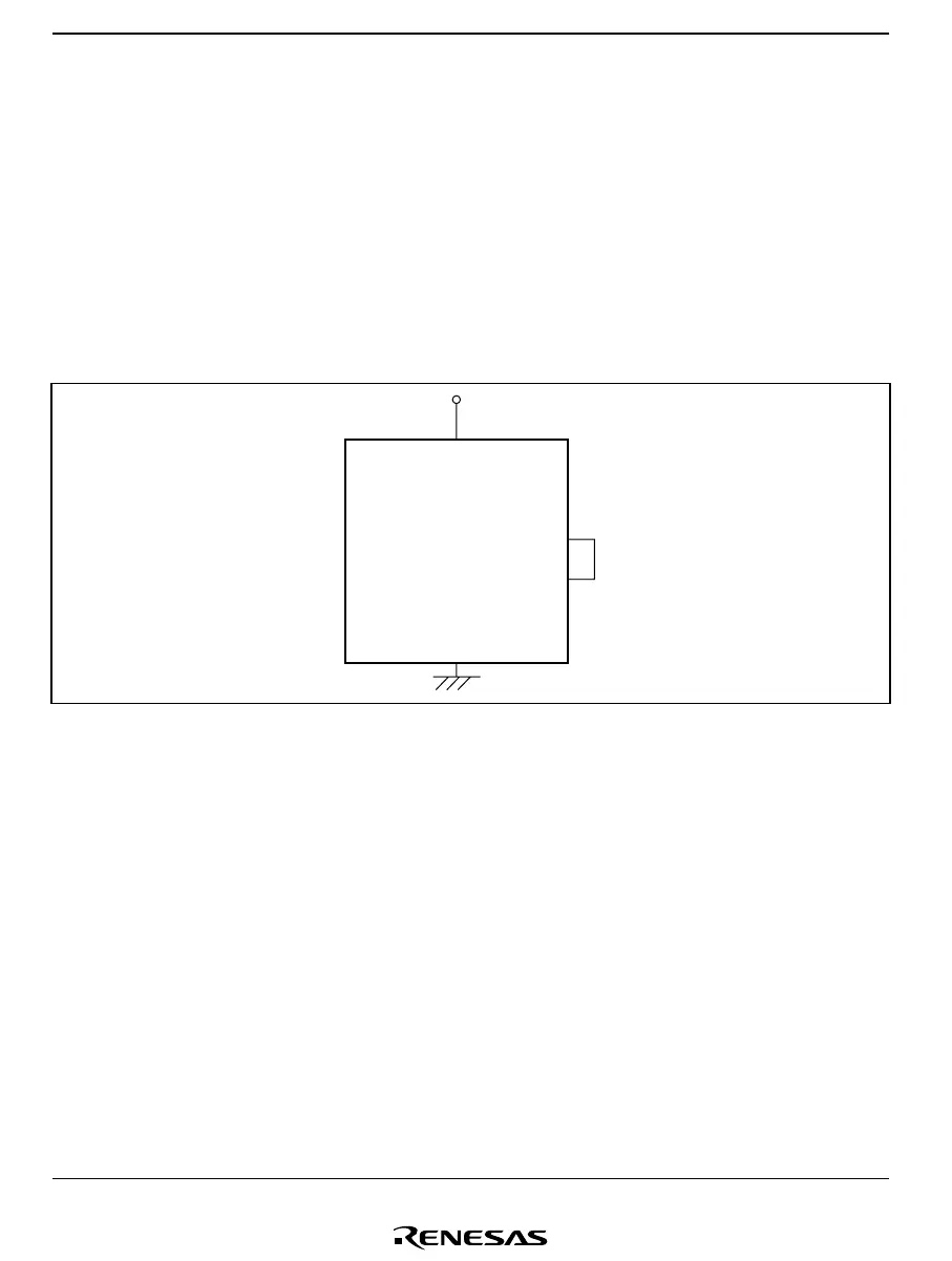
a. Using 1/2 duty
When 1/2 duty is used, interconnect pins V
2
and V
3
as shown in figure 13.2.
V
CC
V
1
V
2
V
3
V
SS
Figure 13.2 Handling of LCD Drive Power Supply when Using 1/2 Duty
b. Large-panel display
As the impedance of the built-in power supply split-resistance is large, it may not be suitable
for driving a large panel. If the display lacks sharpness when using a large panel, refer to
section 13.3.4, Boosting the LCD Drive Power Supply. When static or 1/2 duty is selected, the
common output drive capability can be increased. Set CMX to 1 when selecting the duty
cycle. In this mode, with a static duty cycle pins COM
4
to COM
1
output the same waveform,
and with 1/2 duty the COM
1
waveform is output from pins COM
2
and COM
1
, and the COM
2
waveform is output from pins COM
4
and COM
3
.

 Loading...


