Section 14 Power-On Reset and Low-Voltage Detection Circuits (H8/38124 Group Only)
Rev. 7.00 Mar 10, 2005 page 436 of 652
REJ09B0042-0700
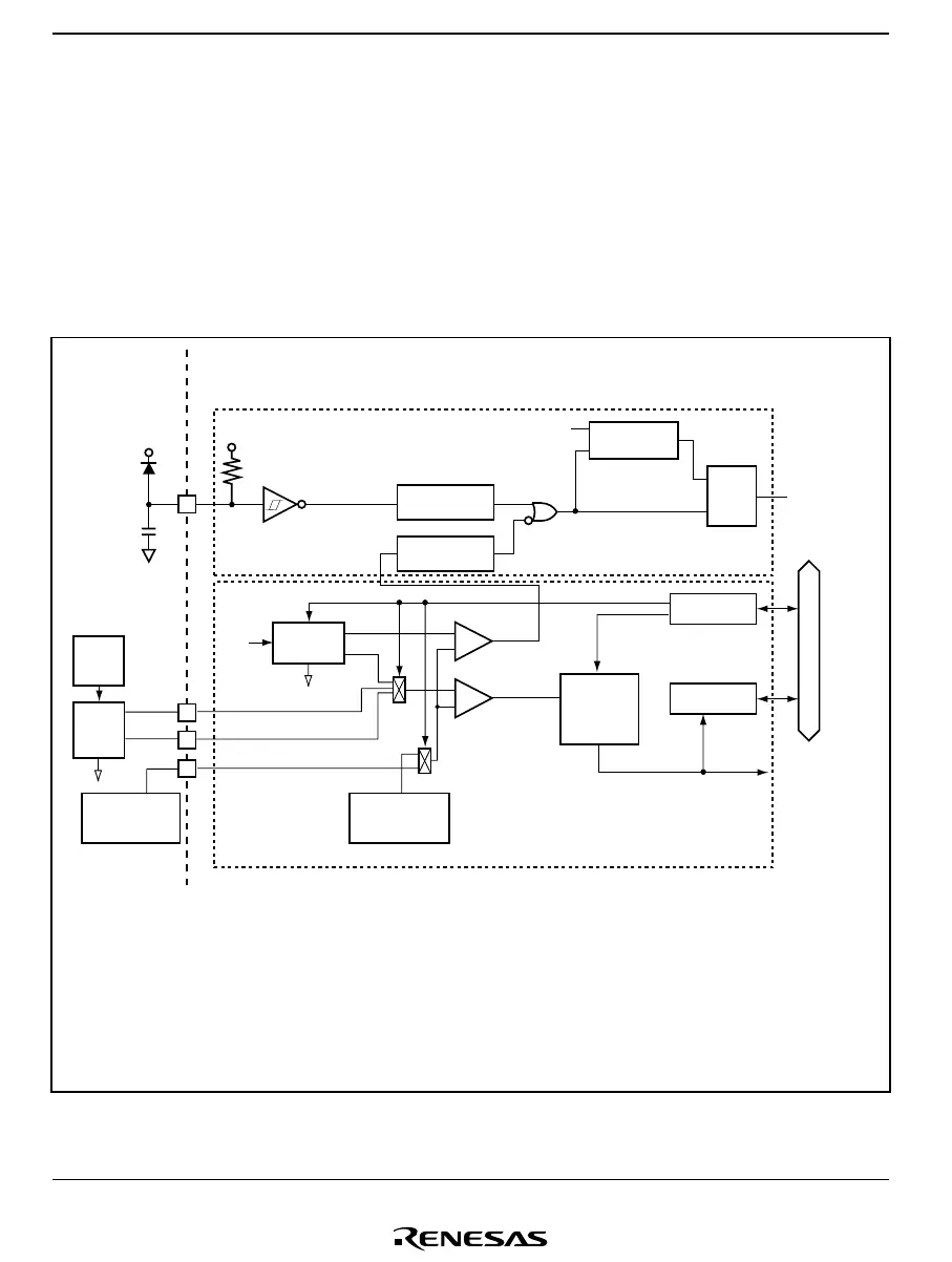
Two pairs of detection levels for reset generation voltage are available: when only the LVDR
circuit is used, or when the LVDI and LVDR circuits are both used. In addition, power supply
rise/drop detection voltages and a detection voltage reference voltage may be input from an
external source, allowing the detection level to be set freely by the user.
14.1.2 Block Diagram
A block diagram of the power-on reset circuit and low-voltage detection circuit are shown in
figure 14.1.
PSS:
LVDCR:
LVDSR:
LVDRES:
LVDINT:
Vreset:
Vint:
extD:
extU:
Vref:
Prescaler S
Low-voltage-detection control register
Low-voltage-detection status register
Low-voltage-detection reset signal
Low-voltage-detection interrupt signal
Reset detection voltage
Power-supply fall/rise detection voltage
Power supply drop detection voltage input pin
Power supply rise detection voltage input pin
Reference voltage input pin
RES
φ
CK
R
PSS
Vcc
R
S
Q
OVF
Vreset
Vref
extU
extD
Vint
External
reference voltage
generator
On-chip
reference voltage
generator
[Legend]
LVDRES
Interrupt
control
circuit
LVDCR
LVDSR
Internal reset
signal
Power-on reset circuit
Low-voltage detection circuit
Interrupt
request
LVDINT
Noise
canceler
Noise
canceler
+
−
+
−
Ladder
resistor
External
ladder
resistor
External
power
supply
Internal data bus
Figure 14.1 Diagram of Power-On Reset Circuit and Low-Voltage Detection Circuit

 Loading...


