Section 13 LCD Controller/Driver
Rev. 7.00 Mar 10, 2005 page 428 of 652
REJ09B0042-0700
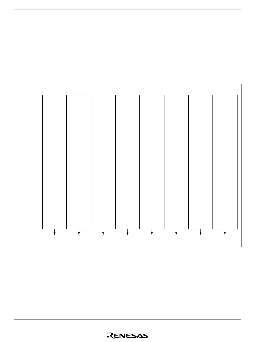
13.3.2 Relationship between LCD RAM and Display
The relationship between the LCD RAM and the display segments differs according to the duty
cycle. LCD RAM maps for the different duty cycles are shown in figures 13.3 to 13.6.
After setting the registers required for display, data is written to the part corresponding to the duty
using the same kind of instruction as for ordinary RAM, and display is started automatically when
turned on. Word- or byte-access instructions can be used for RAM setting.
Bit 7 Bit 6 Bit 5 Bit 4 Bit 3 Bit 2 Bit 1 Bit 0
SEG2 SEG2 SEG2 SEG2 SEG1 SEG1 SEG1 SEG1H'F740
H'F74F
SEG31SEG32SEG32SEG32SEG32 SEG31 SEG31 SEG31
COM4 COM3 COM2 COM1 COM4 COM3 COM2 COM1
Figure 13.3 LCD RAM Map (1/4 Duty)

 Loading...


