Section 13 LCD Controller/Driver
Rev. 7.00 Mar 10, 2005 page 416 of 652
REJ09B0042-0700
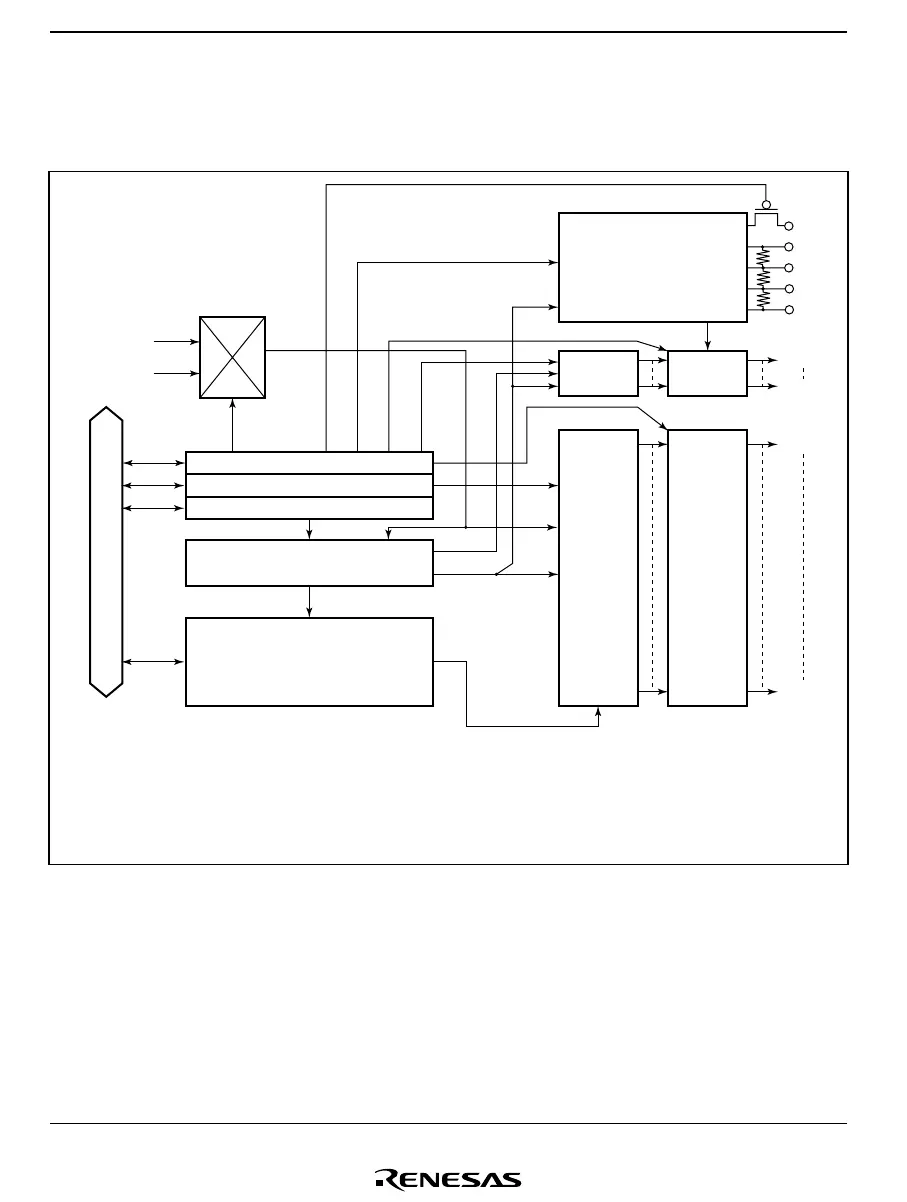
13.1.2 Block Diagram
Figures 13.1(1) and 13.1(2) show a block diagram of the LCD controller/driver.
φ/256 to φ/2
φ
W
SEG
n
LPCR
LCR
LCR2
Display timing generator
LCD RAM
(16 bytes)
Internal data bus
32-bit shift
register
LCD drive power supply
Segment
driver
Common
data latch
Common
driver
V
1
V
2
V
3
V
SS
COM
1
COM
4
SEG
32
SEG
1
[Legend]
LPCR: LCD port control register
LCR: LCD control register
LCR2: LCD control register 2
V
CC
Figure 13.1(1) Block Diagram of H8/38024, H8/38024S, and H8/38024F-ZTAT Group
LCD Controller/Driver

 Loading...


