Section 5 Power-Down Modes
Rev. 7.00 Mar 10, 2005 page 132 of 652
REJ09B0042-0700
t
cyc
t
subcyc
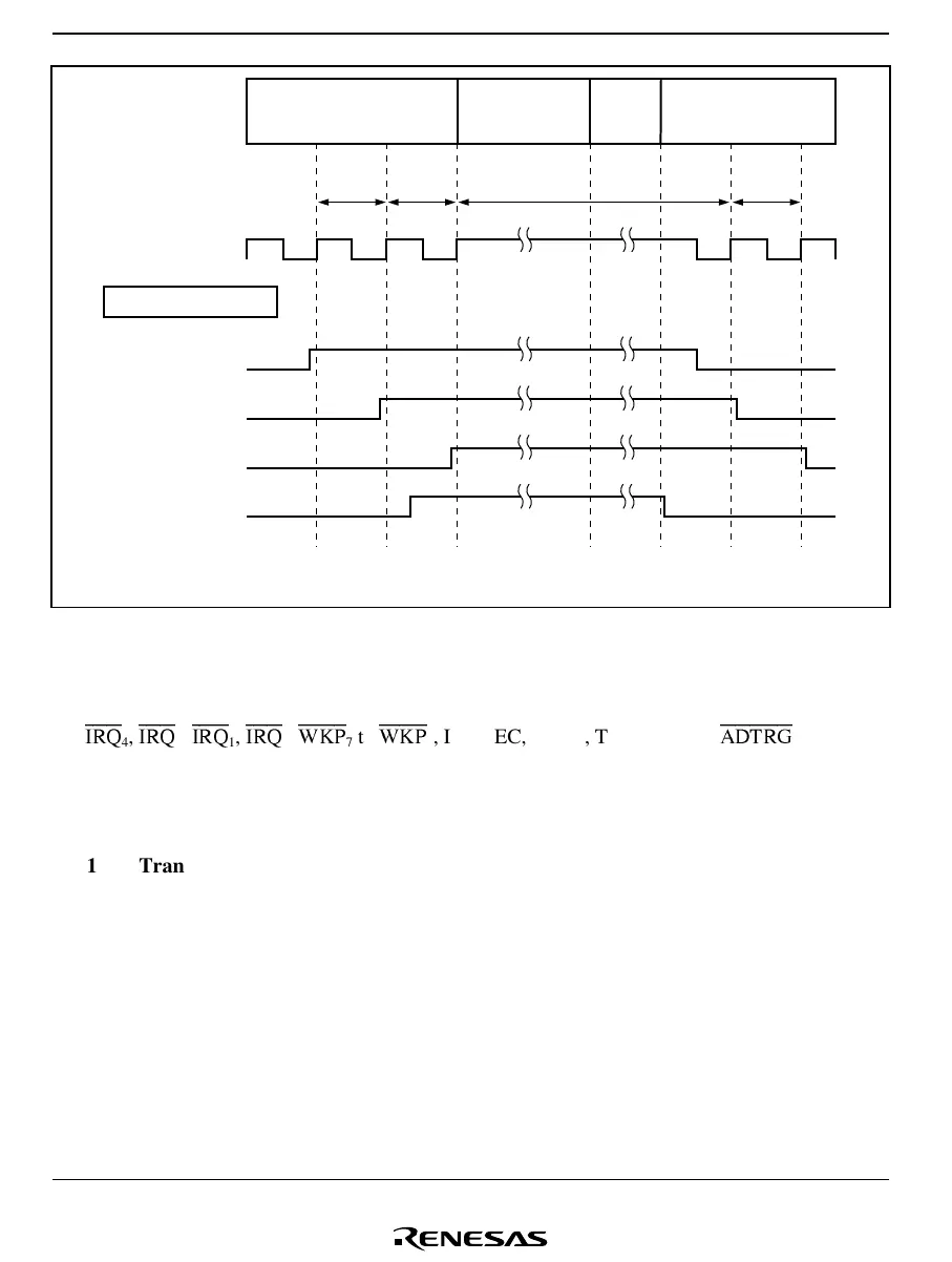
Operating
mode
φ or φ
SUB
Capture possible:
case 1
Capture possible:
case 2
Capture possible:
case 3
Capture not
possible
Interrupt by different
signal
External input signal
Active (high-speed,
medium-speed) mode
or subactive mode
Active (high-speed,
medium-speed) mode
or subactive mode
Standby mode
or watch mode
Wait for
oscillation
to settle
t
cyc
t
subcyc
t
cyc
t
subcyc
t
cyc
t
subcyc
Figure 5.3 External Input Signal Capture when Signal Changes before/after
Standby Mode or Watch Mode
4. Input pins to which these notes apply:
IRQ
4
,
IRQ
3
,
IRQ
1
,
IRQ
0
,
WKP
7
to
WKP
0
, IRQAEC, TMIC, TMIF, TMIG,
ADTRG
.
5.4 Watch Mode
5.4.1 Transition to Watch Mode
The system goes from active or subactive mode to watch mode when a SLEEP instruction is
executed while the SSBY bit in SYSCR1 is set to 1 and bit TMA3 in TMA is set to 1.
In watch mode, operation of on-chip peripheral modules is halted except for timer A, timer F,
timer G, AEC and the LCD controller/driver (for which operation or halting can be set) is halted.
As long as a minimum required voltage is applied, the contents of CPU registers, the on-chip
RAM and some registers of the on-chip peripheral modules, are retained. I/O ports keep the same
states as before the transition.

 Loading...


