Section 12 A/D Converter
Rev. 7.00 Mar 10, 2005 page 401 of 652
REJ09B0042-0700
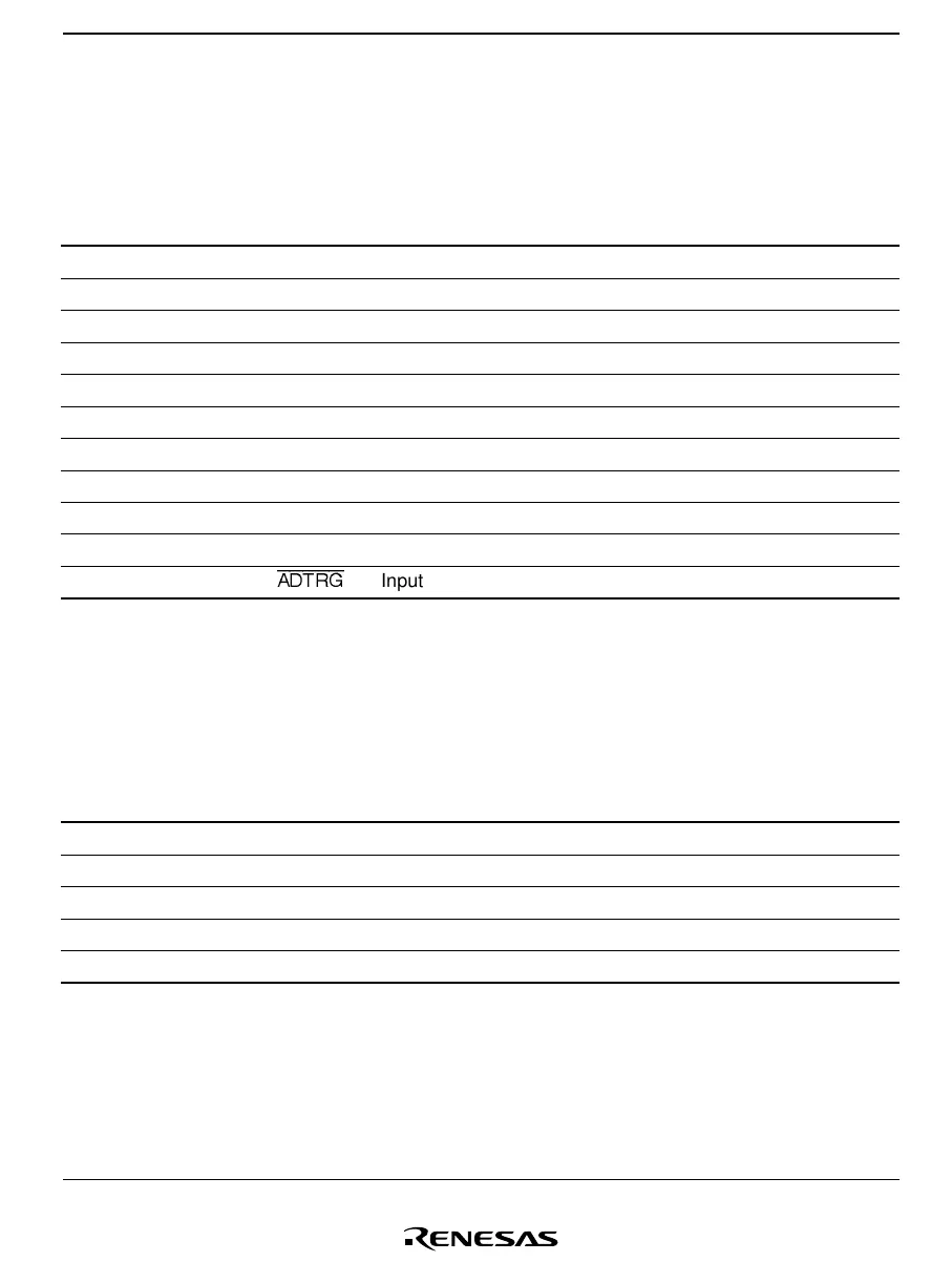
12.1.3 Pin Configuration
Table 12.1 shows the A/D converter pin configuration.
Table 12.1 Pin Configuration
Name Abbr. I/O Function
Analog power supply AV
CC
Input Power supply and reference voltage of analog part
Analog ground AV
SS
Input Ground and reference voltage of analog part
Analog input 0 AN
0
Input Analog input channel 0
Analog input 1 AN
1
Input Analog input channel 1
Analog input 2 AN
2
Input Analog input channel 2
Analog input 3 AN
3
Input Analog input channel 3
Analog input 4 AN
4
Input Analog input channel 4
Analog input 5 AN
5
Input Analog input channel 5
Analog input 6 AN
6
Input Analog input channel 6
Analog input 7 AN
7
Input Analog input channel 7
External trigger input
ADTRG
Input External trigger input for starting A/D conversion
12.1.4 Register Configuration
Table 12.2 shows the A/D converter register configuration.
Table 12.2 Register Configuration
Name Abbr. R/W Initial Value Address
A/D mode register AMR R/W H'30 H'FFC6
A/D start register ADSR R/W H'7F H'FFC7
A/D result register H ADRRH R Not fixed H'FFC4
A/D result register L ADRRL R Not fixed H'FFC5
Clock stop register 1 CKSTPR1 R/W H'FF H'FFFA

 Loading...


