Section 14 Power-On Reset and Low-Voltage Detection Circuits (H8/38124 Group Only)
Rev. 7.00 Mar 10, 2005 page 440 of 652
REJ09B0042-0700
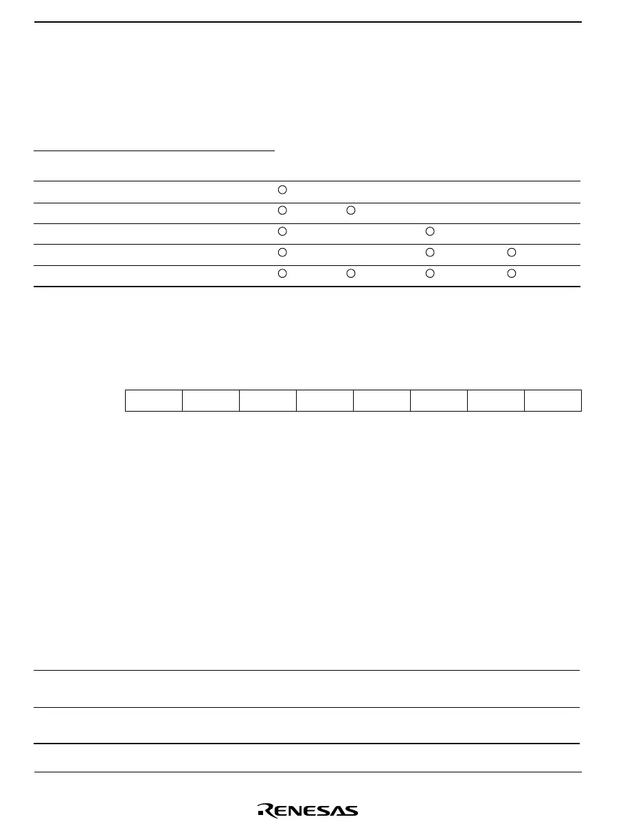
Table 14.3 shows the relationship between LVDCR settings and function selections. Refer to table
14.3 when making settings to LVDCR.
Table 14.3 LVDCR Settings and Function Selections
LVDCR Setting Value
LVDE LVDSEL LVDRE LVDDE LVDUE
Power-on
Reset
Low-Voltage
Detection
Reset
Low-Voltage
Detection
Voltage Drop
Interrupt
Low-Voltage
Detection
Voltage Rise
Interrupt
0 **** —— —
11 1 0 0 ——
10 0 1 0 — —
10 0 1 1 —
10 1 1 1
Note: Setting values marked with an asterisk (*) are invalid.
14.2.2 Low-Voltage Detection Status Register (LVDSR)
Bit 76543210
OVF — — — VREFSEL — LVDDF LVDUF
Initial value 0
*
000000
*
0
*
Read/Write R/W R/W R/W R/W R/W R/W R/W R/W
Note: * These bits initialized by resets trigged by LVDR.
LVDSR is an 8-bit read/write register. It is used to control external input selection, indicates when
the reference voltage is stable, and indicates if the power supply voltage goes below or above a
specified range.
Bit 7—LVD Reference Voltage Stabilized Flag (OVF)
This bit indicates when the low-voltage detection counter (LVDCNT) overflows.
Bit 7
OVF Description
0
[Clearing condition] (initial value)
When 0 is written after reading 1
1
[Setting condition]
When the low-voltage detection counter (LVDCNT) overflows

 Loading...


