Section 4 Clock Pulse Generators
Rev. 7.00 Mar 10, 2005 page 104 of 652
REJ09B0042-0700
System
clock
oscillator
Subclock
oscillator
Subclock
divider
(1/2, 1/4, 1/8)
System
clock
divider
(1/2)
System
clock
divider
Prescaler S
(13 bits)
Prescaler W
(5 bits)
OSC
1
Latch
On-chip
oscillator
Internal reset signal (other than watchdog timer or low-voltage detect
circuit reset)
C
DQ
IRQAEC
OSC
2
X
1
X
2
System clock pulse generator
Subclock pulse generator
φ
OSC
(f
OSC
)
R
OSC
φ
W
(f
W
)
φ
W
/2
φ
W
/4
φ
SUB
φ
W
φ/2
to
φ/8192
φ
φ
W
/2
φ
W
/4
φ
W
/8
to
φ
W
/128
φ
W
/8
φ
OSC
/2
φ
OSC
/16
φ
OSC
/32
φ
OSC
/64
φ
OSC
/128
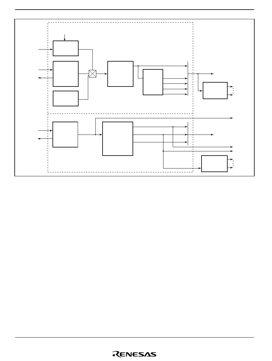
Figure 4.2 Block Diagram of Clock Pulse Generators (H8/38124 Group)
4.1.2 System Clock and Subclock
The basic clock signals that drive the CPU and on-chip peripheral modules are φ and φ
SUB
. Four
of the clock signals have names: φ is the system clock, φ
SUB
is the subclock, φ
OSC
is the oscillator
clock, and φ
W
is the watch clock.
The clock signals available for use by peripheral modules are φ/2, φ/4, φ/8, φ/16, φ/32, φ/64,
φ/128, φ/256, φ/512, φ/1024, φ/2048, φ/4096, φ/8192, φ
W
, φ
W
/2, φ
W
/4, φ
W
/8, φ
W
/16, φ
W
/32, φ
W
/64,
and φ
W
/128. The clock requirements differ from one module to another.

 Loading...


