Section 3 Exception Handling
Rev. 7.00 Mar 10, 2005 page 79 of 652
REJ09B0042-0700
3.3.2 Interrupt Control Registers
Table 3.3 lists the registers that control interrupts.
Table 3.3 Interrupt Control Registers
Name Abbreviation R/W Initial Value Address
IRQ edge select register IEGR R/W — H'FFF2
Interrupt enable register 1 IENR1 R/W — H'FFF3
Interrupt enable register 2 IENR2 R/W — H'FFF4
Interrupt request register 1 IRR1 R/W
*
— H'FFF6
Interrupt request register 2 IRR2 R/W
*
— H'FFF7
Wakeup interrupt request register IWPR R/W
*
H'00 H'FFF9
Wakeup edge select register WEGR R/W H'00 H'FF90
Note: * Write is enabled only for writing of 0 to clear a flag.
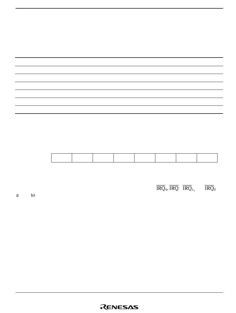
IRQ Edge Select Register (IEGR)
Bit
Initial value
Read/Write
7
1
6
1
5
1
4
IEG4
0
R/W
3
IEG3
0
R/W
0
IEG0
0
R/W
2
W
1
IEG1
0
R/W
IEGR is an 8-bit read/write register used to designate whether pins
IRQ
4
,
IRQ
3
,
IRQ
1
,
and
IRQ
0
are set to rising edge sensing or falling edge sensing. For the IRQAEC pin edge sensing
specifications, see section 9.7, Asynchronous Event Counter (AEC).
Bits 7 to 5—Reserved
Bits 7 to 5 are reserved: they are always read as 1 and cannot be modified.

 Loading...


