Section 13 LCD Controller/Driver
Rev. 7.00 Mar 10, 2005 page 433 of 652
REJ09B0042-0700
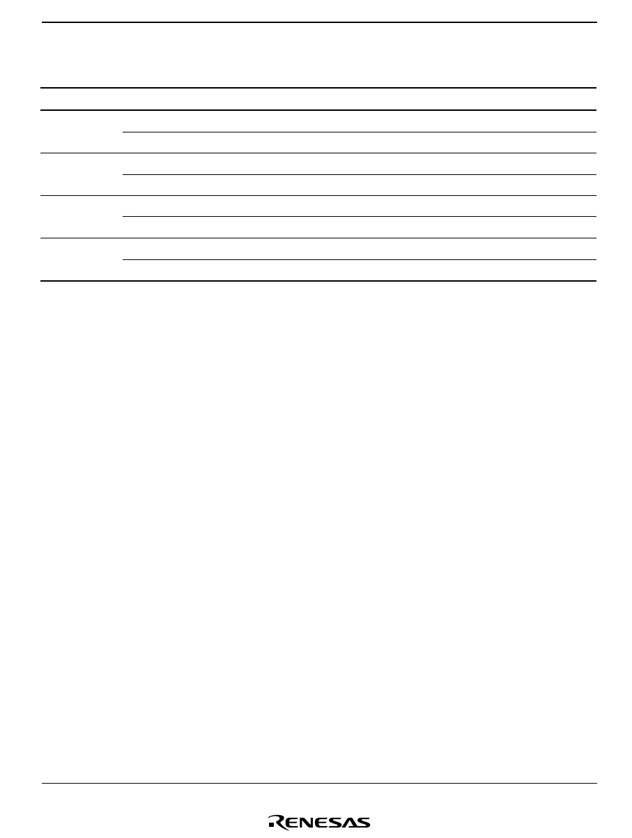
Table 13.3 Output Levels
Data 0011
M 0101
Static Common output V
1
V
SS
V
1
V
SS
Segment output V
1
V
SS
V
SS
V
1
1/2 duty Common output V
2
, V
3
V
2
, V
3
V
1
V
SS
Segment output V
1
V
SS
V
SS
V
1
1/3 duty Common output V
3
V
2
V
1
V
SS
Segment output V
2
V
3
V
SS
V
1
1/4 duty Common output V
3
V
2
V
1
V
SS
Segment output V
2
V
3
V
SS
V
1
M: LCD alternation signal
13.3.3 Operation in Power-Down Modes
This LSI the LCD controller/driver can be operated even in the power-down modes. The
operating state of the LCD controller/driver in the power-down modes is summarized in table
13.4.
In subactive mode, watch mode, and subsleep mode, the system clock oscillator stops, and
therefore, unless φw, φw/2, or φw/4 has been selected by bits CKS3 to CKS0, the clock will not be
supplied and display will halt. Since there is a possibility that a direct current will be applied to
the LCD panel in this case, it is essential to ensure that φw, φw/2, or φw/4 is selected. In active
(medium-speed) mode, the system clock is switched, and therefore CKS3 to CKS0 must be
modified to ensure that the frame frequency does not change.

 Loading...


