Section 11 10-Bit PWM
Rev. 7.00 Mar 10, 2005 page 392 of 652
REJ09B0042-0700
11.1.4 Register Configuration
Table 11.2 shows the register configuration of the 10-bit PWM.
Table 11.2 Register Configuration
Name Abbr. R/W Initial Value Address
PWM1 control register PWCR1 W H'FC/H'F8
*
H'FFD0
PWM1 data register U PWDRU1 W H'FC H'FFD1
PWM1 data register L PWDRL1 W H'00 H'FFD2
PWM2 control register PWCR2 W H'FC/H'F8
*
H'FFCD
PWM2 data register U PWDRU2 W H'FC H'FFCE
PWM2 data register L PWDRL2 W H'00 H'FFCF
Clock stop register 2 CKSTPR2 R/W H'FF H'FFFB
Note: * Implemented on H8/38124 Group only.
11.2 Register Descriptions
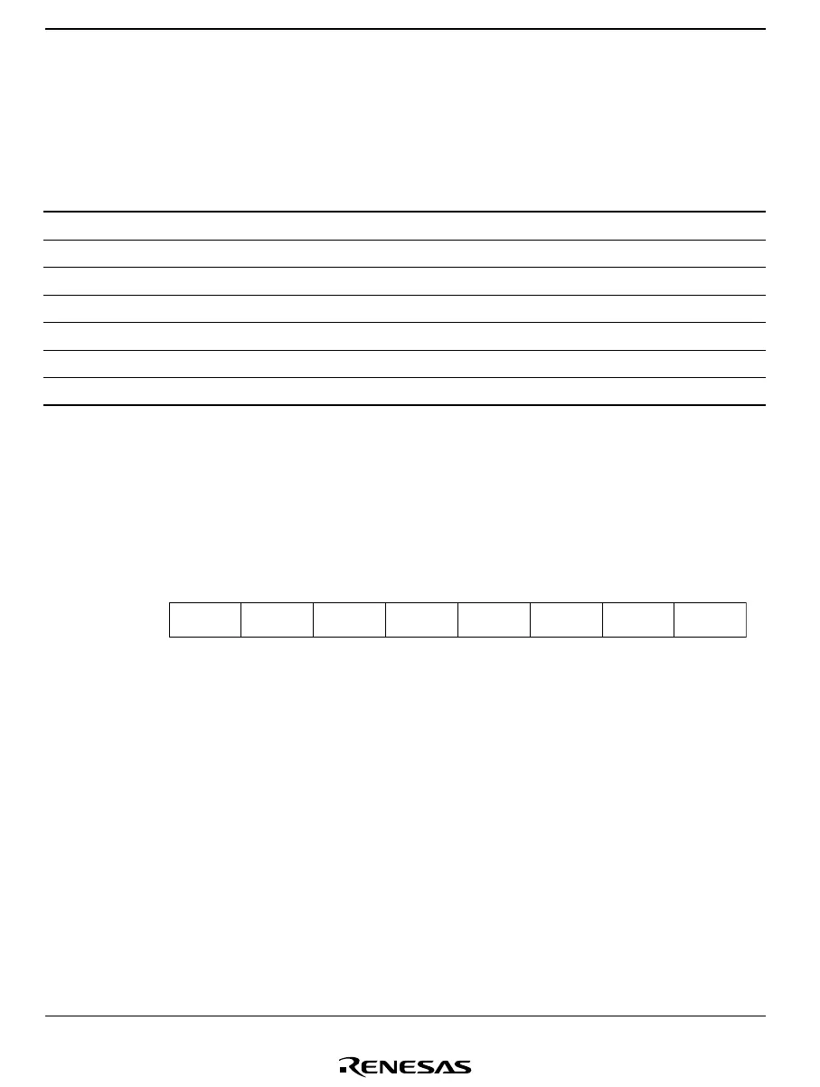
11.2.1 PWM Control Register (PWCRm)
Bit
Initial value
Read/Write
Note: * Implemented on H8/38124 Group only.
7
1
6
1
5
1
4
1
3
1
0
PWCRm0
0
W
2
1/0
*
/W
*
1
PWCRm1
0
W
/
PWCRm2
*
On the H8/38024 Group, H8/38024F-ZTAT Group, and H8/38024S Group, PWCRm is an 8-bit
write-only register for input clock selection.
Upon reset, PWCRm is initialized to H'FC. On the H8/38124 Group, PWCRm is an 8-bit write-
only register used to select the input clock and PWM output type. At reset PWCRm is initialized
to H'F8.

 Loading...


