Section 12 A/D Converter
Rev. 7.00 Mar 10, 2005 page 402 of 652
REJ09B0042-0700
12.2 Register Descriptions
12.2.1 A/D Result Registers (ADRRH, ADRRL)
Bit 7 6 5 4 3
ADRRH ADRRL
021 76543 021
Initial value
Read/Write
Unde-
fined
R
Unde-
fined
R
Unde-
fined
R
Unde-
fined
R
Unde-
fined
R
Unde-
fined
R
Unde-
fined
R
Unde-
fined
R
Unde-
fined
R
Unde-
fined
R
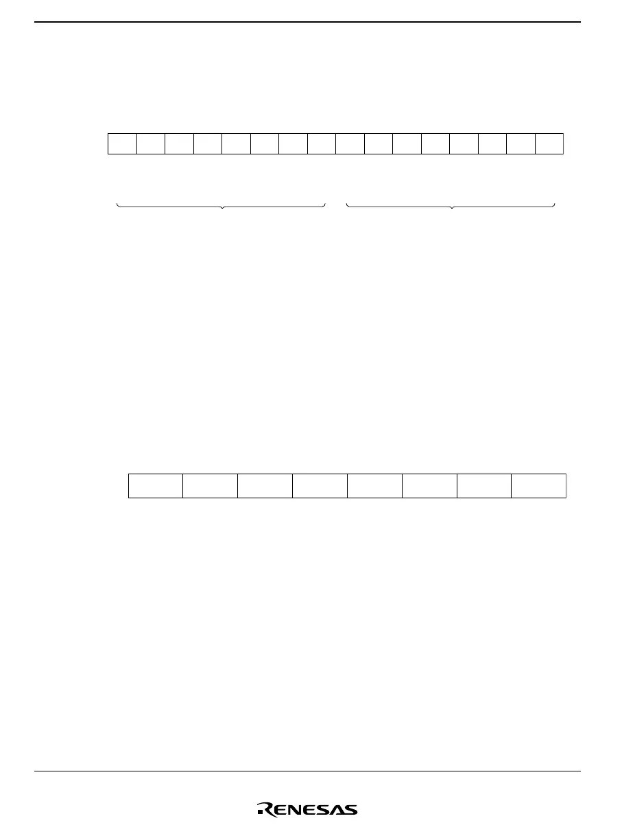
ADR9 ADR8 ADR7 ADR6 ADR5 ADR2ADR4 ADR3 ADR1 ADR0
ADRRH and ADRRL together comprise a 16-bit read-only register for holding the results of
analog-to-digital conversion. The upper 8 bits of the data are held in ADRRH, and the lower 2
bits in ADRRL.
ADRRH and ADRRL can be read by the CPU at any time, but the ADRRH and ADRRL values
during A/D conversion are not fixed. After A/D conversion is complete, the conversion result is
stored as 10-bit data, and this data is held until the next conversion operation starts.
ADRRH and ADRRL are not cleared on reset.
12.2.2 A/D Mode Register (AMR)
Bit
Initial value
Read/Write
7
CKS
0
R/W
6
TRGE
0
R/W
5
1
4
1
3
CH3
0
R/W
0
CH0
0
R/W
2
CH2
0
R/W
1
CH1
0
R/W
AMR is an 8-bit read/write register for specifying the A/D conversion speed, external trigger
option, and the analog input pins.
Upon reset, AMR is initialized to H'30.

 Loading...


