Section 6 ROM
Rev. 7.00 Mar 10, 2005 page 155 of 652
REJ09B0042-0700
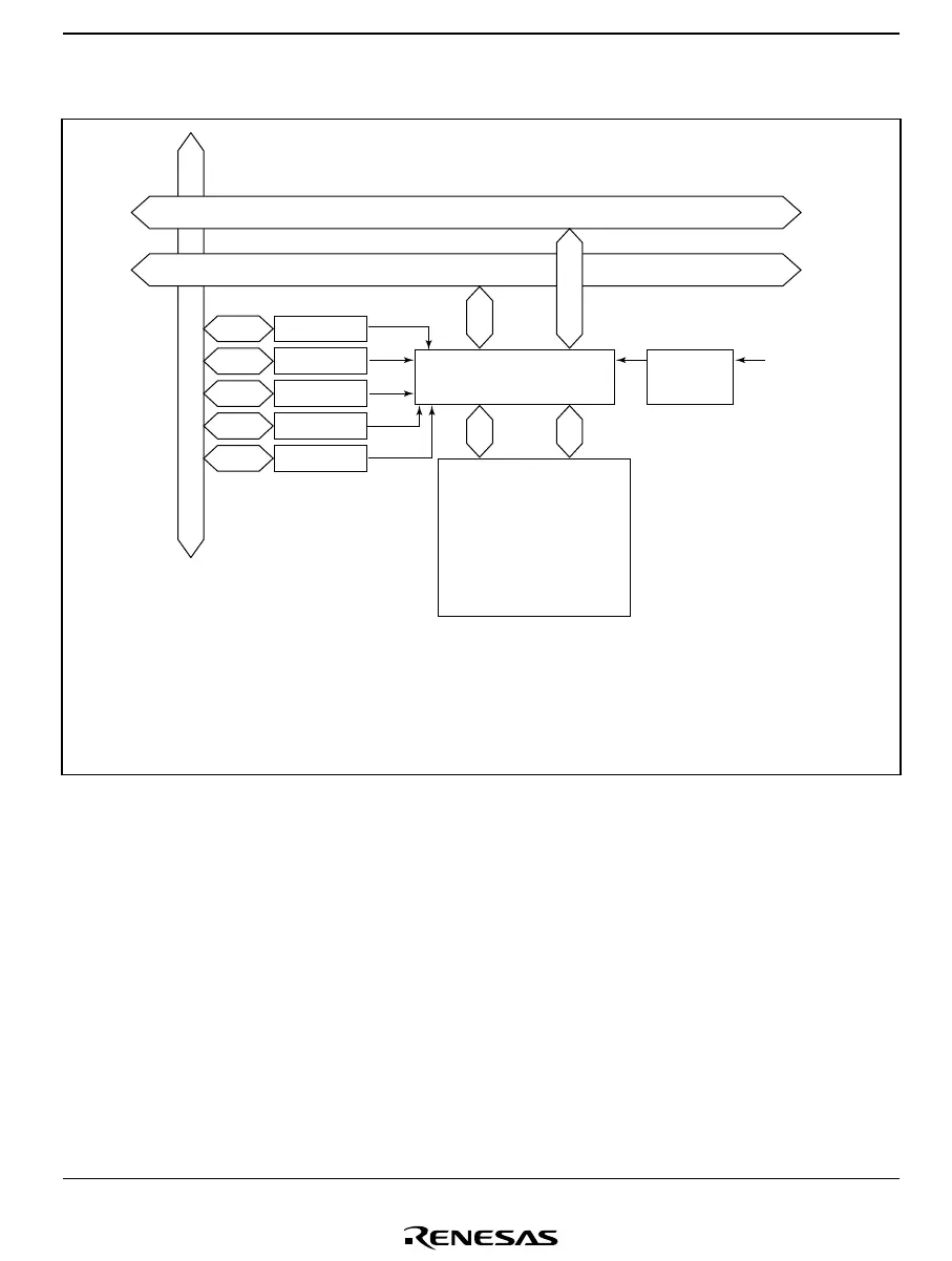
6.5.2 Block Diagram
Internal address bus
Module bus
Internal data bus (16 bits)
FLMCR1
Bus interface/controller
Operating
mode
TES pin
P95 pin
P34 pin
[Legend]
FLMCR1: Flash memory control register 1
FLMCR2: Flash memory control register 2
EBR: Erase block register
FLPWCR: Flash memory power control register
FENR: Flash memory enable register
FLMCR2
EBR
FLPWCR
FENR
Flash memory
Figure 6.7 Block Diagram of Flash Memory

 Loading...


