Section 5 Power-Down Modes
Rev. 7.00 Mar 10, 2005 page 124 of 652
REJ09B0042-0700
Bit 3—Low Speed on Flag (LSON)
This bit chooses the system clock (φ) or subclock (φ
SUB
) as the CPU operating clock when watch
mode is cleared. The resulting operation mode depends on the combination of other control bits
and interrupt input.
Bit 3
LSON Description
0 The CPU operates on the system clock (φ) (initial value)
1 The CPU operates on the subclock (φ
SUB
)
Bit 2—Reserved
Bit 2 is reserved: it is always read as 1 and cannot be modified.
Bits 1 and 0—Active (Medium-Speed) Mode Clock Select (MA1, MA0)
Bits 1 and 0 choose φ
osc
/128, φ
osc
/64, φ
osc
/32, or φ
osc
/16 as the operating clock in active (medium-
speed) mode and sleep (medium-speed) mode. MA1 and MA0 should be written in active (high-
speed) mode or subactive mode.
Bit 1
MA1
Bit 0
MA0 Description
00φ
osc
/16
01φ
osc
/32
10φ
osc
/64
11φ
osc
/128 (initial value)
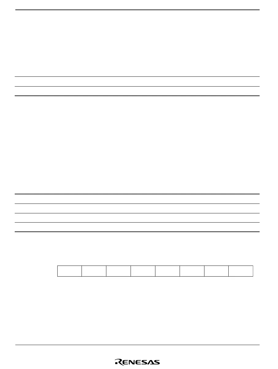
System Control Register 2 (SYSCR2)
Bit
Initial value
Read/Write
7
1
6
1
5
1
4
NESEL
1
R/W
3
DTON
0
R/W
0
SA0
0
R/W
2
MSON
0
R/W
1
SA1
0
R/W
SYSCR2 is an 8-bit read/write register for power-down mode control.
Bits 7 to 5—Reserved
These bits are reserved; they are always read as 1, and cannot be modified.

 Loading...


