Section 9 Timers
Rev. 7.00 Mar 10, 2005 page 285 of 652
REJ09B0042-0700
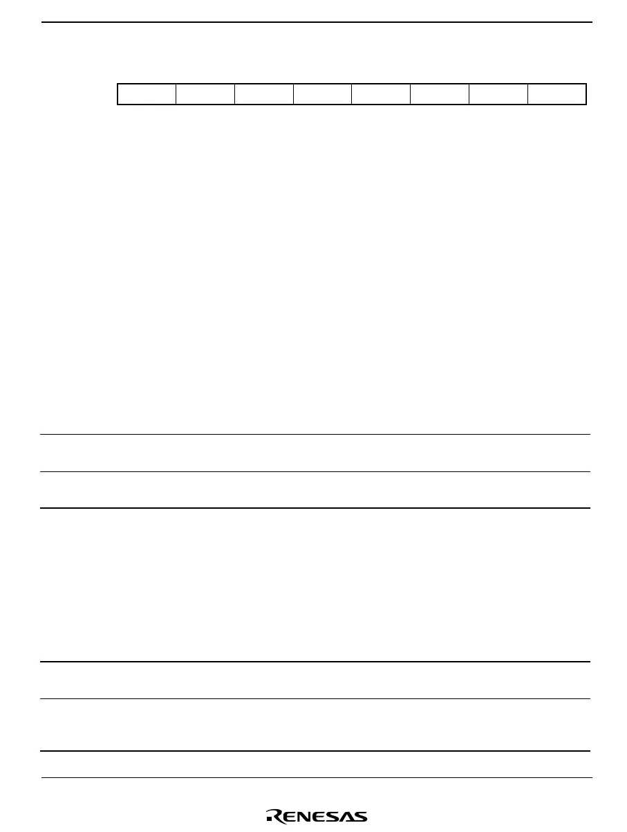
Timer Mode Register G (TMG)
OVFH CCLR0 CKS1 CKS0OVFL OVIE IIEGS CCLR1
76543210
0
0000000
R/(W)
*
R/W R/W R/W
R/(W)
*
R/W R/W
R/W
Bit:
Initial value:
Read/Write:
Note: * Bits 7 and 6 can only be written with 0, for flag clearing.
TMG is an 8-bit read/write register that performs TCG clock selection from four internal clock
sources, counter clear selection, and edge selection for the input capture input signal interrupt
request, controls enabling of overflow interrupt requests, and also contains the overflow flags.
TMG is initialized to H'00 upon reset.
Bit 7—Timer Overflow Flag H (OVFH)
Bit 7 is a status flag indicating that TCG has overflowed from H'FF to H'00 when the input capture
input signal is high. This flag is set by hardware and cleared by software. It cannot be set by
software.
Bit 7
OVFH Description
0 Clearing condition:
After reading OVFH = 1, cleared by writing 0 to OVFH (initial value)
1 Setting condition:
Set when input capture input signal is high level and TCG overflows from H'FF to H'00
Bit 6—Timer Overflow Flag L (OVFL)
Bit 6 is a status flag indicating that TCG has overflowed from H'FF to H'00 when the input capture
input signal is low, or in interval operation. This flag is set by hardware and cleared by software.
It cannot be set by software.
Bit 6
OVFL Description
0 Clearing condition:
After reading OVFL = 1, cleared by writing 0 to OVFL (initial value)
1 Setting condition:
Set when TCG overflows from H'FF to H'00 while input capture input signal is high
level or during interval operation

 Loading...


