Saia-Burgess Controls AG
Manual I/O-modules for PCD1 │ PCD2 series │ Document 27-600 – Release ENG09 │ 2019-05-01
6-18
I/O modules PCD3
Digital input modules, electrically isolated from the I/O Bus
6
6.3 Digital input modules, electrically isolated from the I/O Bus
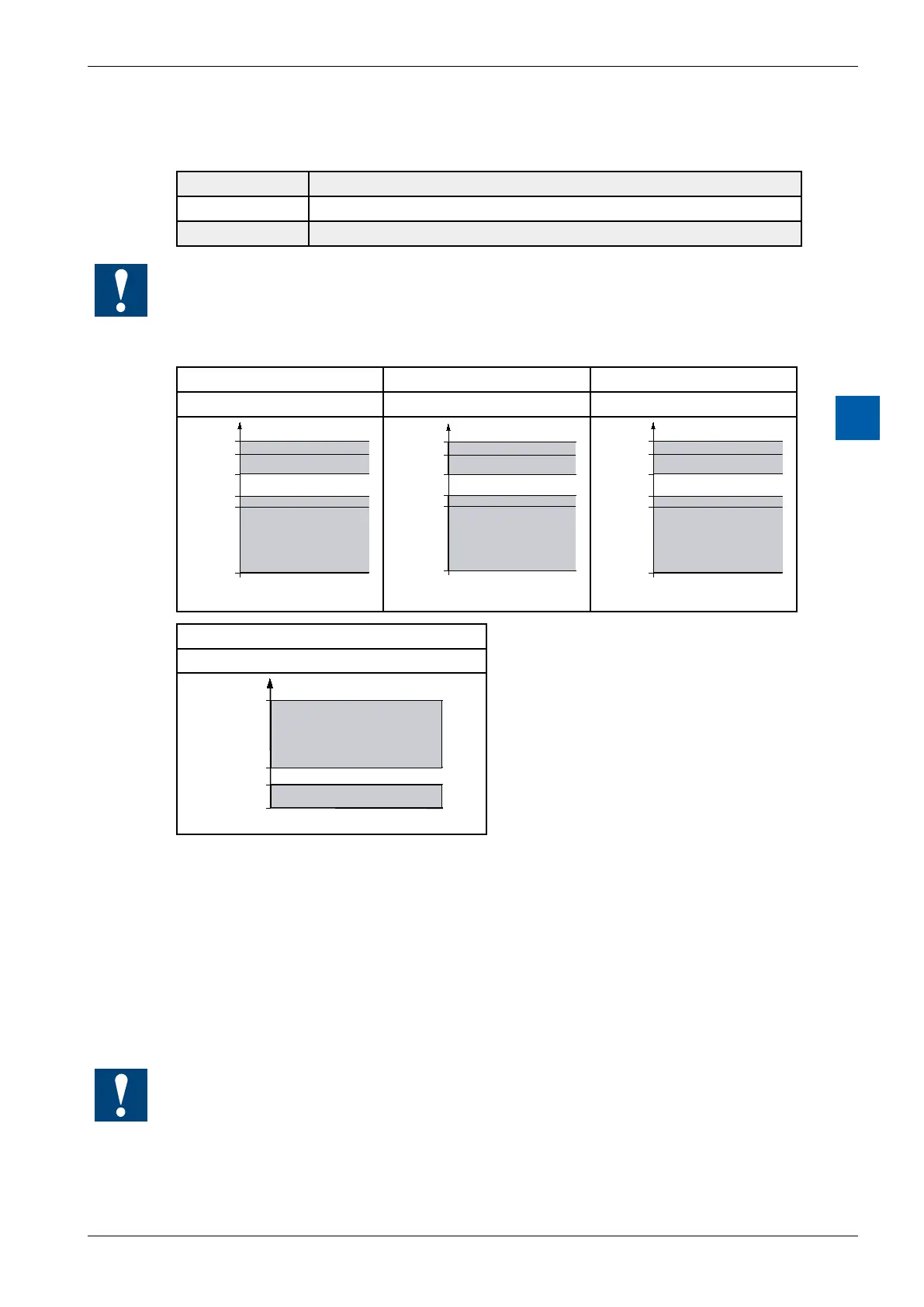
PCD3.E500 6 inputs for 115 … 230 VAC
PCD3.E610 8 inputs 24 VDC, 10 ms
PCD3.E613 8 inputs 48 VDC, 9 ms
Electrical isolation of inputs to the Saia PCD
®
.
The channels are not isolated from each other
Denition of input signals
for 5 VDC for 24 VDC for 48 VDC
(on request) PCD3.E610 PCD3.E613
7 VDC
5 VDC
2.5 VDC
0 VDC
1 VDC
-7 VDC
1
0
30 V
DC
24 V
DC
15 V
DC
0 V
DC
5 V
DC
-30 V
DC
1
0
60 VDC
48 VDC
30 VDC
0 VDC
10 VDC
-60 VDC
1
0
for 115 – 230 VAC
PCD3.E500
1
0
250 V
AC
80 V
AC
40 V
AC
0 V
AC
Installation instructions
For reasons of safety it is not permissible to connect low voltages (up to 50V)
and higher voltages (50 … 250 V) to the same module.
If a Saia PCD
®
module is connected to a higher voltage (50 … 250 V), approved
components for this voltage must be used for all elements that are electrically con-
nected to the system.
Using higher voltage (50…250V), all connections to the relay contacts must be
connected on the same circuit, i.e. in such a way that they are all protected against
one AC phase by one common fuse. Each load circuit may however be fused
individually.
I/O modules and I/O terminal blocks may only be plugged in and removed when the
Saia PCD
®
and the external +24V are disconnected from the power supply.