Saia-Burgess Controls AG
Manual I/O-modules for PCD1 │ PCD2 series │ Document 27-600 – Release ENG09 │ 2019-05-01
6-19
I/O modules PCD3
PCD3.E500
6
6.3.1 PCD3.E500, 6 digital inputs, electrically isolated from the I/O Bus
Application
Module with 6 electrically isolated inputs for alternating current. The inputs are set
up for source operation and have one common "COM" terminal. Only the positive
half-wave of the alternating current is used.
Technical data
Number of inputs 6 electrically isolated from the CPU,
source operation, all inputs to the module in
the same phase
Input voltage 115/230 V 50/60 Hz, sinusoidal
(80 to 250 VAC)
Input current 115 VAC: 5…6 mA (wattless current)
230 VAC: 10…12 mA (wattless current)
Input delay
switch-on:
switch-o:
typ.10ms;max.20ms
typ.20ms;max.30ms
LED supplied directly from input current
Resistance to interference acc. to IEC
801-4
4 kV under direct coupling
2 kV under capacitive coupling
(whole trunk group)
Electrical isolation voltage 2000 VAC, 1 min
Electrical isolation resistance 100MΩ/500VDC
Optocoupler isolation voltage 2.5 kV
Internal current consumption:
(from +5 V bus)
< 1 mA
Internal current consumption:
(from V+ bus)
0 mA
External current consumption: 0 mA
Terminals:
Plug-in 10-pole spring terminal block
(4 405 4954 0) or pluggable 10-pole screw terminal
block (4 405 4955 0), both for wires up to 2.5 mm²
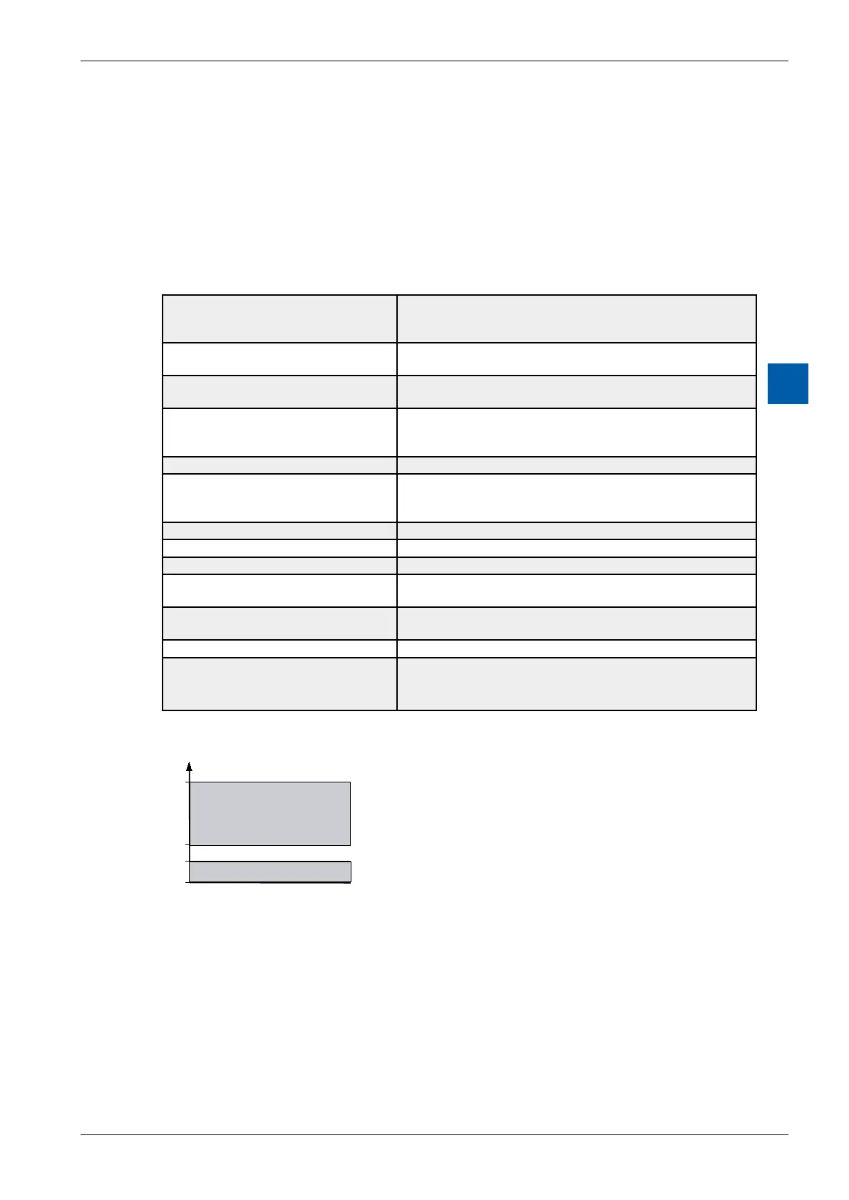
Switchon/olevel:
250VAC
80VAC
40VAC
0VAC
1
0