Saia-Burgess Controls AG
Manual I/O-modules for PCD1 │ PCD2 series │ Document 27-600 – Release ENG09 │ 2019-05-01
5-45
I/O modules PCD1|PCD2
PCD2.B100
5
5.6.1 PCD2.B100, 2 inputs + 2 outputs
+ 4 digital inputs/outputs (selectable)
Application
Economical combined input/output module with:
● 2inputs24 VDC/8 ms for source operation, electrically connected
● 2transistoroutputs0.5A/5 … 32VDC, electrically connected, not short circuit
protected, and
● 4combinedinputs/outputs24 VDC/8msor0.5A/5 … 32VDC on common I/O
terminals.
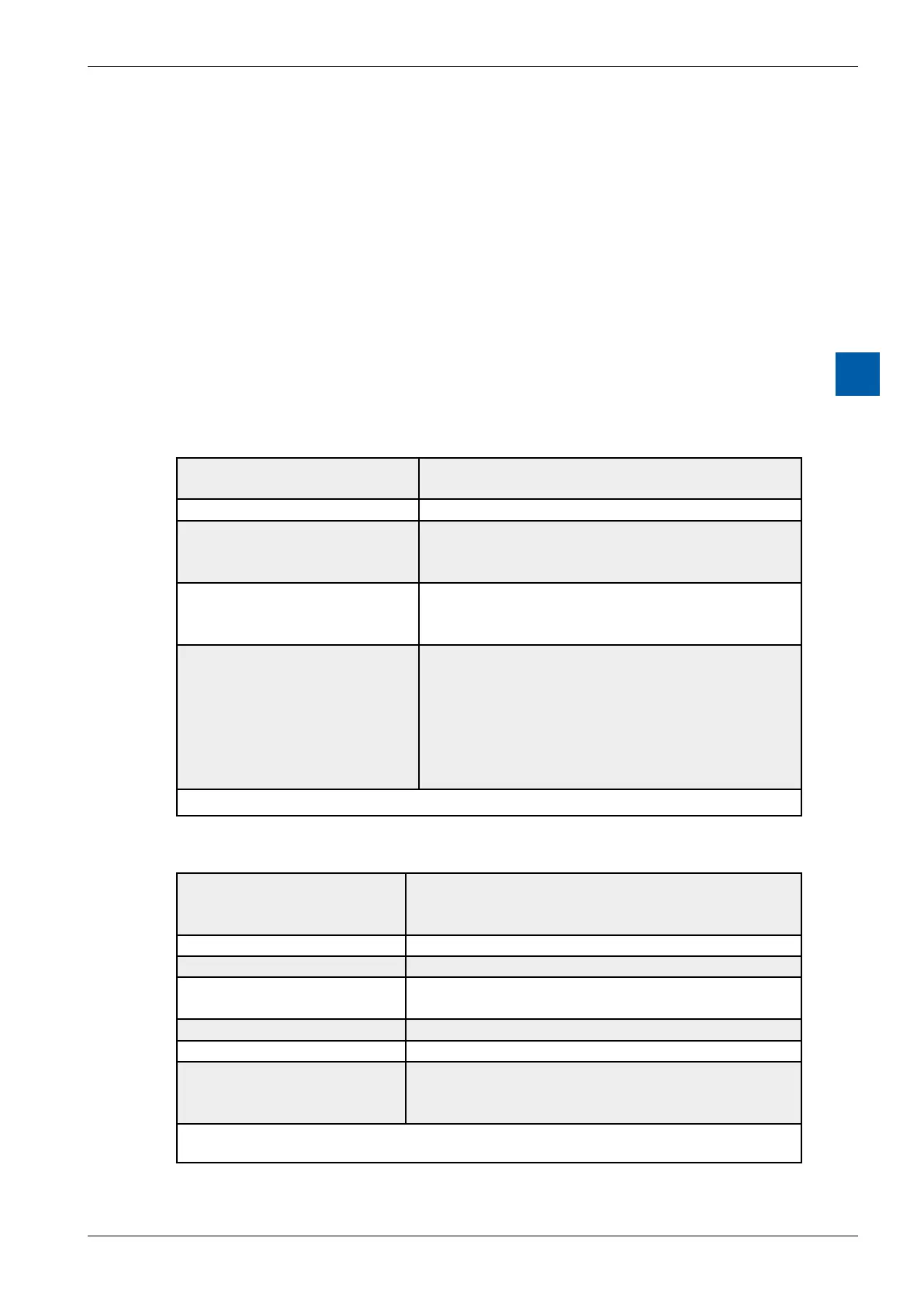
Technical data on inputs
Number of inputs: 6 (2 + 4), electrically connected,
source operation
Input voltage: 24 VDC smoothed or pulsed
2 inputs E0 and E1
low-range:
high-range:
-30 … +5V
+15 … +32V
4inputsE/A2 … E/A5
low-range:
high-range:
-0.5 … +5V*)
+15 … +32V
All 6 inputs:
low-high switching threshold:
high-low switching threshold:
hysteresis:
input current (24 VDC):
switching delay 0-1 (24 VDC):
switching delay 1-0 (24 VDC):
13 V typically
6 V typically
7 V typically
7 mA typically
8 ms typically
8 ms typically
*)Negativevoltageisrestrictedbytheprotectivediode(I
max
= 0.5 A)
Technical data on outputs
Number of outputs: 6 (2 + 4) electrically connected,
source operation
not short circuit protected
Current: 5 … 500mAsteadyload
Voltage range: 5 … 32VDC*)
Voltage drop: < 0.3 V at 500 mA for A6 and A7
<0.7Vat500mAforE/A2 … E/A5
Total current per module: 3 A steady load
Switch-on delay: 10 µs typically
Switch-odelay: 50 µs typically (100 µs max.), (ohmic load
5 … 500mA),longerforinductiveloadbecauseof
protective diode.
*) If it is intended to read the status of a combined output, the external voltage must be at least
17 VDC, as both the status and the LED are displayed via the input.