Saia-Burgess Controls AG
Manual I/O-modules for PCD1 │ PCD2 series │ Document 27-600 – Release ENG09 │ 2019-05-01
7-13
PCD2.B160 & PCD3.B160
Direct input or output access in IL
7
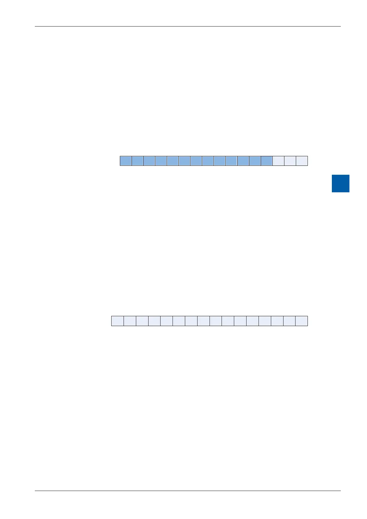
7.5.1.5 RD_MODULE_STATUS
This symbol returns the status of the module. When there is no error all the bits are
low. Symbol clears automatically after reading.
Communication Error: Sets when an error occurs during the communication between
the PCD & the module.
Output Error: Sets when outputs are in high impedance because of short circuit,
overcurrent or no power on connector.
FlashError: Setswhenmodulefailedtosavecongurationintoash.
15:0
RD_MODULE_STATUS
Output Error
Communication Error
Flash Error
IL example:
RDPW IO.Slot0.IOAccess.RD_MODULE_STATUS
Status
7.5.1.6 WR_DIGITAL_OUTPUT_0TO15
This symbol is used to write the outputs. Each bit corresponds to one output. If you
writeabitwhoseI/Oisnotconguredinoutput,nothinghappens.
15:0
WrDigitalOutput
O 0
O 1
O 2
O 3
O 4
O 5
O 6
O 7
O 8
O 9
O 10
O 11
O 12
O 13
O 14
O 15
IL example:
LD Data_Out
0FFFFH
WRPW IO.Slot0.IOAccess.WR_DIGITAL_OUTPUT_0TO15
Data_Out