Saia-Burgess Controls AG
Manual I/O-modules for PCD1 │ PCD2 series │ Document 27-600 – Release ENG09 │ 2019-05-01
5-22
I/O modules PCD1|PCD2
PCD2.E61x
5
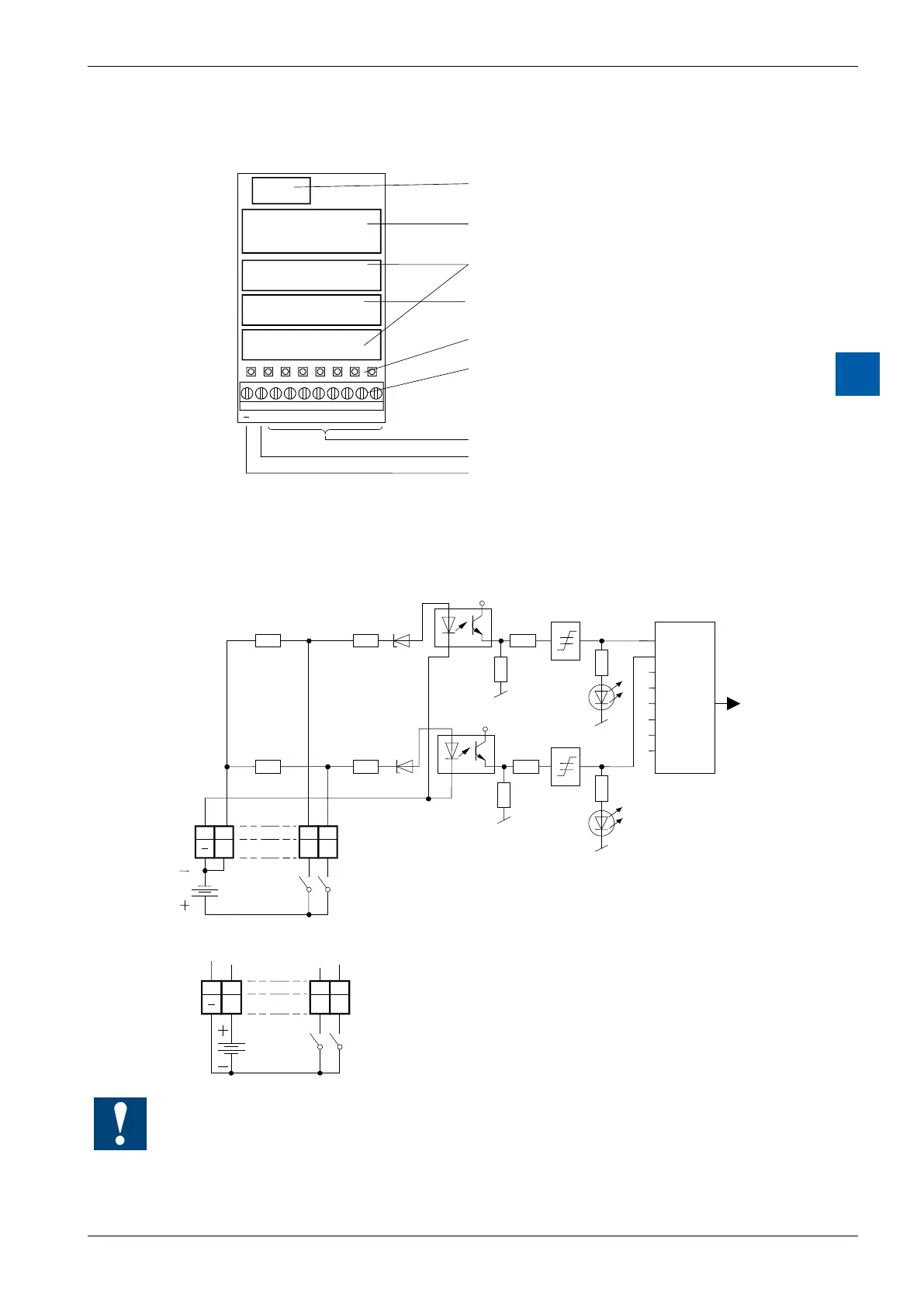
LEDs and connection terminals
9 8 7 6 5 4 3 2 1 0
E0E1E2E3E4E5E6E7L
Bus connector
Bus interface and
threshold switch
Input circuits
Electrical isolation by
Optocouplers
LEDs
Screw terminals
Inputs E0 to E7
Input load resistors
User ground (-)
Input circuits and terminal designation
Depending on external wiring, this module may be used for source or sink opera-
tion.Source operation (positive logic):
+5V
E0
E1
6k6
6k6
11k
11k
+5V
E0 E1 L
8 9 0 1
I/O Bus
Ue : 48 VDC
24 VDC
5 VDC
Switch closed
(positive at input) : Input state "H" = LED on
Switch open : Input state "L" = LED off
PCD Bus
Sink operation (negative logic):
E0 E1
1
L
8 9 0
Switch closed
(negative at input) : Input state "H" = LED off
Switch open : Input state "L" = LED on
Ue : 48 VDC
24 VDC
5 VDC
Watchdog:Thismodulecanbeusedonallbaseaddresses;thereisnointerac-
tion with the watchdog on the CPUs. For details, please refer to the section A4
“Hardware Watchdog”, which describes the correct use of the watchdog in con-
junction with PCD components.