Saia-Burgess Controls AG
Manual I/O-modules for PCD1 │ PCD2 series │ Document 27-600 – Release ENG09 │ 2019-05-01
5-61
I/O modules PCD1|PCD2
PCD2.W2x0
5
5.8.3 PCD2.W2x0, analogue inputs, 8 channels, 10 bit resolution
Application
With its short conversion time of <50 µs, this module is universally suitable for
recording analogue signals. The only limitations are with weak signals, as with
Pt 100 resistive temperature sensors, or with thermocouples.
Module overview
PCD2.W200 8channelsforsignals0 … 10V
PCD2.W210 8channelsforsignals0 … 20mA
PCD2.W220 8 channels for resistive temperature sensors Pt/Ni 1000
PCD2.W220Z02 8 channels for NTC10 temperature sensors
PCD2.W220Z12 4 channels for signals0 … 10V
4 channels for resistive temperature sensors Pt/Ni 1000
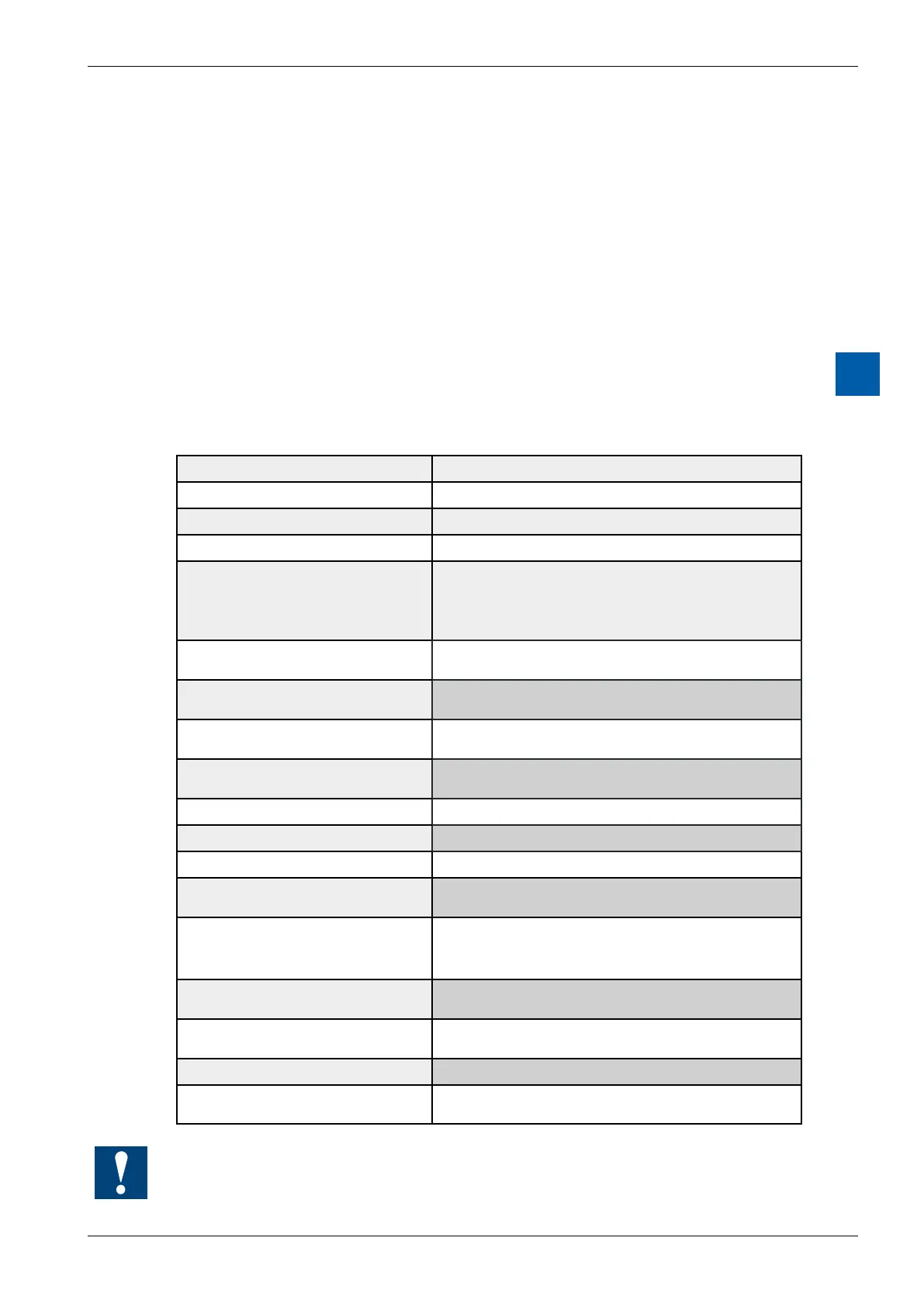
Technical data
Signal ranges: see module overview
Galvanic separation: no
Resolution (digital representation): 10bits(0 … 1023)
Measuring principle: non-dierential,single-ended
Input resistance: 0 … 10V: 80kΩ/0.15%
0 … 20mA: 125Ω/0,1%
Pt/Ni1000: 7,5kΩ/0,1%
NTC10: 10kΩ/0,1%
Maximum signal current for the re-
sistance measurement with W220:
1.5 mA
Accuracy:
(of measured value)
± 3 LSB
Repeating accuracy:
(under same conditions)
within 1 LSB
Temperature error: ± 0.3 % ( ± 3 LSB),
(overtemperaturerangefrom0° … +55°C)
Conversion time A/D: <50 µs
Overvoltage protection: W200/220: ± 50 VDC
Overcurrent protection: W210: ± 40 mA
Burst protection:
(IEC 1000-4-4)
± 1 kV, with unshielded cables
± 2 kV, with shielded cables
Timeconstantofinputlter: W200: typically 5 ms
W210: typically 1 ms
W220 : typically 10 ms
Internal current consumption:
(from +5 V bus)
8 mA (W200/210/220)
Internal current consumption:
(from V+ bus)
5 mA (W200/210)
16 mA (W220)
External current consumption: 0 mA
Terminals: Pluggable 10-pole screw terminal block
(4 405 4847 0), for wires up to 1.5 mm²
A signal with wrong polarity at an input, may cause that the measuring results at
theotherchannelsaresignicantlyfalsied.