Saia-Burgess Controls AG
Manual I/O-modules for PCD1 │ PCD2 series │ Document 27-600 – Release ENG09 │ 2019-05-01
9-3
PCD2.G200
Specications
9
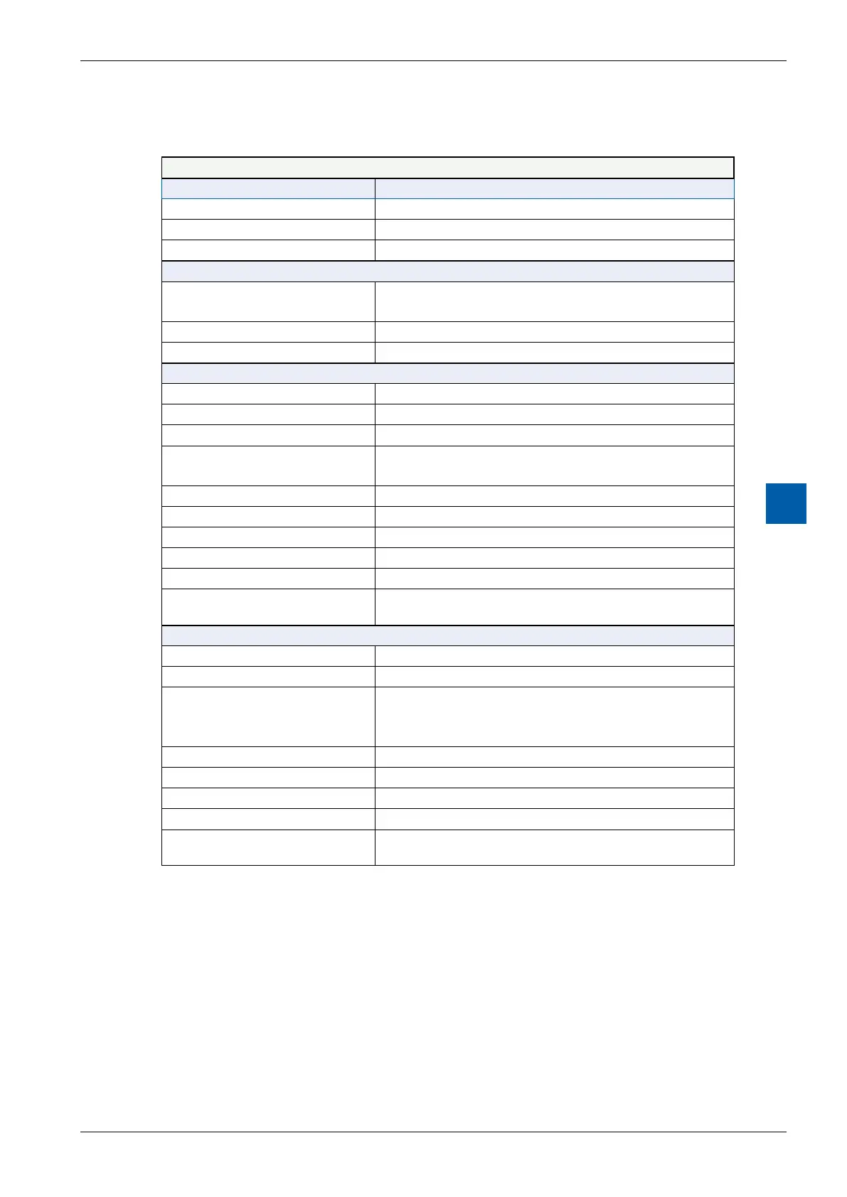
9.2 Specications
Technical data
COMPATIBILITY PCD1, PCD2
Storage temperature – 25…+70°C
Ambient temperature operating 0…+55 °C
Relative air humidity 10…95% r.h. non condensing
POWER
Module power supply voltage +5V and V+ (from I/O-BUS)
And 24V ext. for digital outputs
Current consumption 12 mA on +5V and max. 35 mA on V+
Galvanic separation No
DIGITAL OUTPUTS
Number of outputs 4, electrically connected, source operation
Addressing O 0…3 (+BA)
Voltage range 10…32 VDC, smoothed, max. 10% residual ripple
Output current 5…500 mA (leakage current max. 0,1 mA)
min.loadresistance:48Ω
Short circuit protection yes
Voltage drop max. 0.3 V at 0.5 A
Output delay Typically50μs,max.100μsforresistiveload
Overvoltage protection TVS Diode 39 V
LEDs yes
Terminals 1 plug-in spring-load terminal block, 10-pole, 3.5mm for wir-
ing up to 1 mm², black
DIGITAL INPUTS
Number of inputs 4, electrically connected, source operation
Addressing I 4…7 (+BA)
Input voltage Typ. 24 VDC smoothed or pulsed
H level: 15…30 V
L level: –30…+5 V
Input current typ. 7 mA at 24 VDC (IEC 61131-2, Typ 1)
Input delay typ. 8 ms
Overvoltage protection no (Umax = ±34 V)
LEDs yes
Terminals 1 plug-in spring-load terminal block, 10-pole,
3.5 mm for wiring up to 1 mm², black
Table 1: Technical Data