Saia-Burgess Controls AG
Manual I/O-modules for PCD1 │ PCD2 series │ Document 27-600 – Release ENG09 │ 2019-05-01
9-5
PCD2.G200
Specications
9
9.2.1 Resolution of the analogue inputs
Mode Resolution [analogue] Resolution
[digital]
Read Values
(default)
Voltage
0…+10 V
2.44 mV (linear) 1 mV 0…+10‘000
Current
0…+20 mA
5.14 uA (linear) 1 uA 0…+20‘000
Resistance
0…2'500Ω
0.50…0.80Ω 0.1Ω 0...25’000
Resistance
0…300kΩ
0…10kΩ:
10k…20kΩ:
20k…40kΩ:
40 k…70 kΩ:
70k…100kΩ:
100k…300kΩ:
2…14Ω
14…40Ω
40…130Ω
130…350Ω
350…700Ω
0.7…4.5kΩ
1Ω 0..300’000
Pt 1000 – 50…+400°C: 0.15…0.25°C 0.1°C – 500…4000
Ni 1000 – 60…+200°C: 0.09…0.11°C 0.1°C – 600…2000
Ni 1000 L&S – 60…+200°C: 0.12…0.15°C 0.1°C – 600…2000
Table 3: Resolution of the module
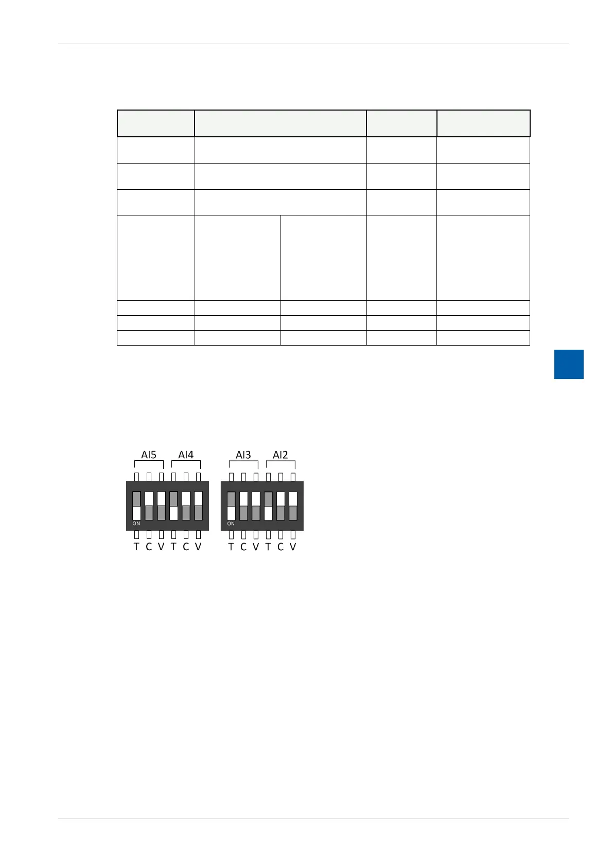
9.2.2 Dip Switch position
The input circuit for the analogue inputs AI2 … AI5 can be selected by mini Dip
switches:
Figure 3: DIP Switches
The modes T (NI/PT1000), C (0…20 mA) or V (0…10 V) are selected by putting
the switch in the down position. Only one switch per channel has to be on, except
in the 0…300kΩrangewheretheTandtheVswitchmustbeon.
Theabovepictureshowsthedefaultsetting(allonT)whereallinputsarecong-
ured in the temperature measurement mode.