Saia-Burgess Controls AG
Manual I/O-modules for PCD1 │ PCD2 series │ Document 27-600 – Release ENG09 │ 2019-05-01
A-3
Appendix
Hardware watchdog
A
A.4 Hardware watchdog
Saia PCD
®
CPUsarettedwithahardwarewatchdogasstandard.ArelayatI/O
address255canbetriggered;thisremainsactivatedaslongasthestatusofO
255 changes periodically at least every 200 ms. Within PG5, FBoxes are provided
for this purpose.
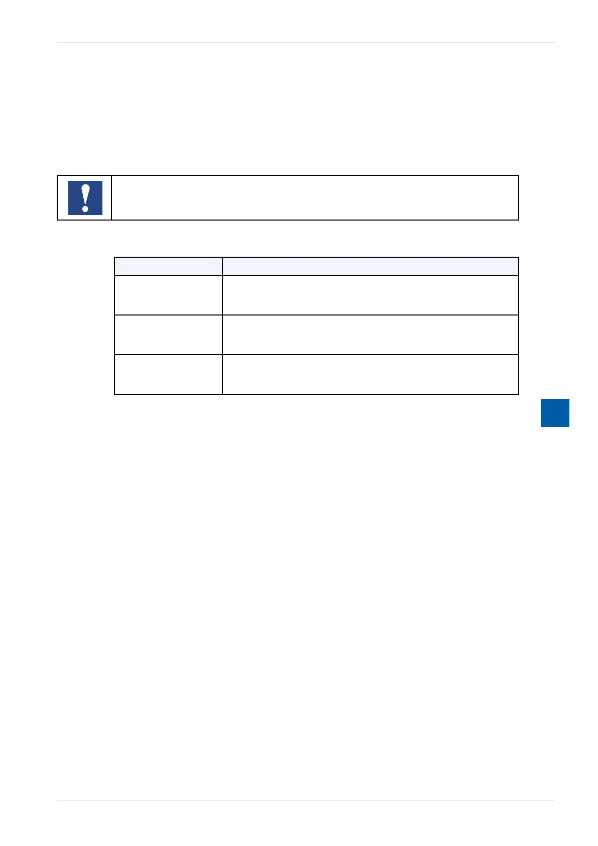
As address 255 is in the normal I/O range, there are restrictions on the permissible I/O
modules in certain sockets:
CPU type
Restrictions
all
(except: see below)
- No analogue, counter and motion control modules on the socket with
base address 240
- Output 255 cannot be used for digital I/O modules
PCD2.M170
- No analogue, counter and motion control modules on the socket with
base address 496
- Output 511 cannot be used for digital I/O modules
PCD2.M480
- No analogue, counter and motion control modules on the socket with
base addresses 752 and 1008
- The outputs 767 and 1023 cannot be used for digital I/O modules