Saia-Burgess Controls AG
Manual I/O-modules for PCD1 │ PCD2 series │ Document 27-600 – Release ENG09 │ 2019-05-01
8-7
PCD2.W380 & PCD3.W380
PCD2/3.W380,8analogcongurableinputs
8
8.1.4 Input wiring
The module is connected with the PCD by the I/O Bus connector. It can be
plugged with all the PCD versions PCD1, PCD2, PCD3. The module is completely
powered from the PCD bus, no external power supply is needed.
The inputs are connected with the module by two 10-pins connectors for cables
up to 1 mm². These connectors are very reliable and providing 2 pins per chan-
nel, one for the input and the other connected to the ground. In each connector,
2 pins are connected to the ground and can be used by user. In each connector,
one of these pins should be used as protective ground connection to avoid immu-
nity problems against external perturbations. A wire with a section of 1 mm² and a
maximum length of 20 cm is recommended for a good PGND connection.
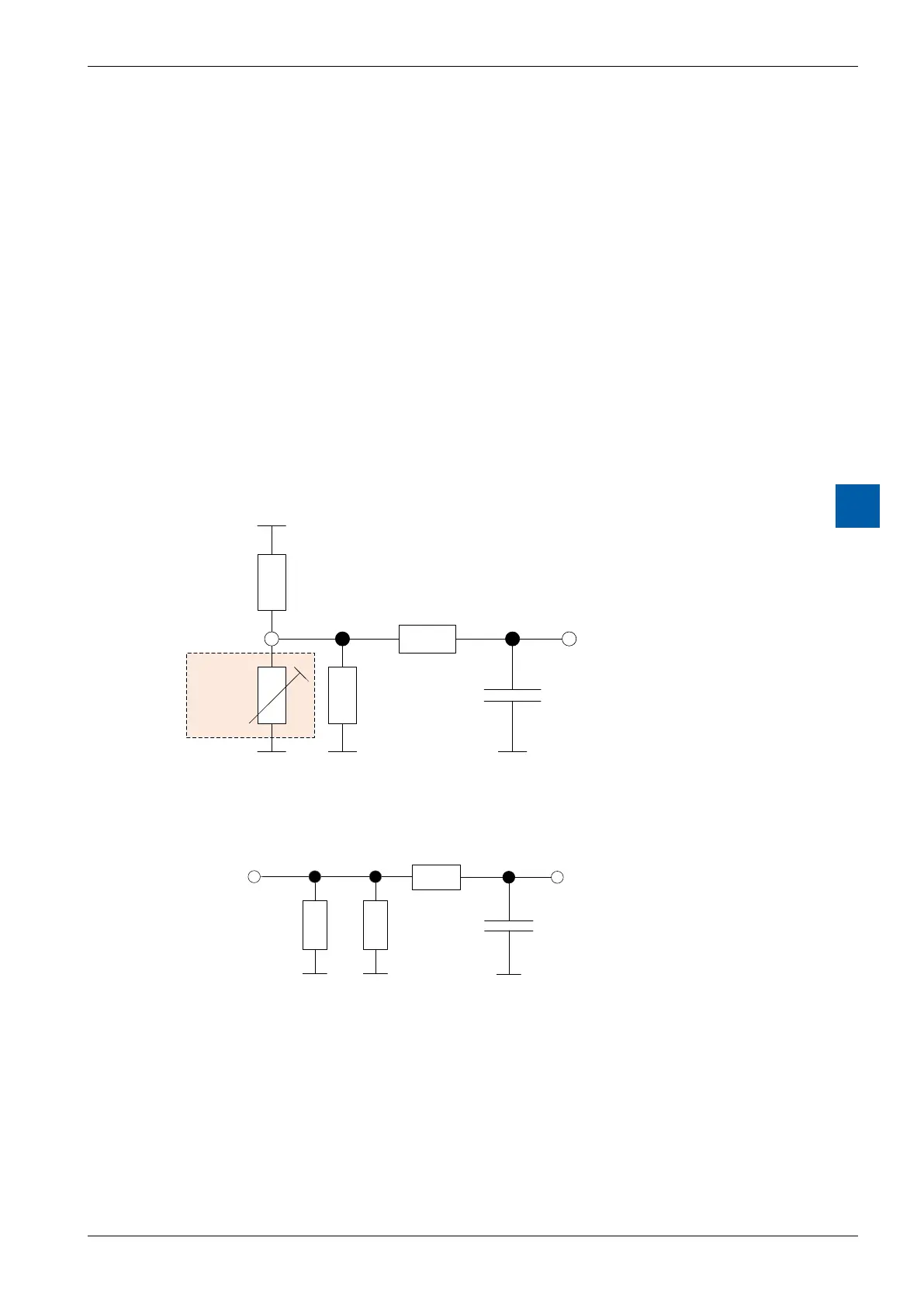
Every measurement mode has an equivalent input stage.
For resistance measurements (temperature sensors), 10 V are provided through a
7.5kΩresistortotheinput.
7k5
4k7
330k
10V
220n
ADC
Temp.
Sensor
Input
Figure 3: Equivalent schematic of input in temperature and resistance mode
Forcurrentmeasurements,ashuntof225Ωisconnectedtotheground.
330k
225
4k7
220n
ADC
Eingang
Figure 4: Equivalent schematic of input in "current" mode